Summary of PIC16F877 ADJUSTABLE DIGITAL POWER SUPPLY CIRCUIT
This article describes a microcontroller-based adjustable digital power supply using the PIC16F877A. It features an output range of 0–25VDC and 0–2.5A, with voltage and current readings displayed on a 16×2 LCD. The system includes preset memory, RS232 communication, forced ventilation controlled by temperature, and input/output separation for stability. The code is written in C using SDCC, and the design supports pushbuttons or encoders for settings.
Parts used in the Adjustable Digital Power Supply:
- Microchip PIC16F877A microcontroller
- LCD display (16x2 with backlight)
- LM324N operational amplifier
- 7805 voltage controller
- Analog pass transistors
- Transformers
- Pushbuttons or mechanical/optical encoder
- Buzzer
- ICSP connector
- RS232 communication interface
- Aluminum housing (3mm)
All details can be adjusted with a microcontroller controlled digital power supply project volts and amps values can be read on the LCD pcb box design 3-dimensional views of the c language prepared by the powder-magazine’s source software projects… Electronics Projects, PIC16F877 Adjustable Digital Power Supply Circuit “microchip projects, microcontroller projects, pic16f877 projects, power electronic projects, power supply project,
All details can be adjusted with a microcontroller controlled digital power supply project volts and amps values can be read on the LCD pcb box design 3-dimensional views of the c language prepared by the powder-magazine’s source software projects belonging to an applied
• Input voltage: 220VAC
• Output voltage: 0 to 25VDC with a current of 0 to 2.5A.
• Regulation Accuracy
• Coarse: 1V / 100mA
• Fine: 100mv / 3mA
• Using the Microchip PIC microcontroller 16F877A leaving available for use 10 port.
• Setting via pushbuttons and mechanical or optical encoder.
• controlled ventilation according to current consumption.
• Reading current consumption, indicating on visual and auditory stream.
• Preset Memory (2.5, 3, 3.3, 5, 9 and 12 volts at 0.5A, 1A and 2.5A).
• Control ventilation temperature reading.
• Power lines separate control circuit of the power section.
• Information for all values through 16×2 LCD with backlight and contrast control.
• Control and RS232 communication with PC or another control board.
• Code written in C compiler SDCC.
DIGITAL POWER SUPPLY TEST
A power supply is one of the most used tools in an electronic laboratory, on the market of various types, with fixed voltage, adjustable analogue, switching power supplies (such as PC) that provide varying voltages (12V-12V , 5V,-5V) with higher amperage. The idea of this power supply is that an analog source is controlled / regulated by the microcontroller easily assembled, inexpensive, feature rich with possibilities for expansion. Since heat dissipation 25V 3 or 4A may compromise some components must have forced ventilation and temperature controlled consumption.
External power lines must be separated from the control part, this reduces any voltage drops due to the use of ventilation, LCD backlight and other devices. To facilitate the construction PCBs will be designed to face without bridges without impeding the use of lower cost methods such as heat transfer toner. The weight of two transformers more electronics in general can lead to the source has an important weight (3kg in my case), is why a 3mm aluminum housing is used.
The programming language must be C since it is easy to understand for the vast majority of people, but with assembler routines when required execution efficiency.
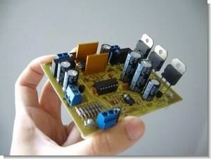
The circuit consists of two parts, one with analog pass transistors, operational LM324N, transformers, controller 7805, inputs and control outputs. The control part consists of the microcontroller, LCD, buzzer, ICSP connector and connectors for input and encoder buttons if you choose to use. Analog part The regulator circuit is dominated by the LM324N component, a quadruple operational that gives us the possibility of a maximum voltage of 32V and the use of resistors low tolerance (in my case I use 5%, but it is recommended 1%).
source sergiols.blogspot.com/ PIC16F877 Adjustable Digital Power Supply Circuit schematic pcb code files Alternative link:
FILE DOWNLOAD LINK LIST (in TXT format): LINKS-6826.zip
Source: PIC16F877 ADJUSTABLE DIGITAL POWER SUPPLY CIRCUIT
- What is the output voltage range of this power supply?
The output voltage ranges from 0 to 25VDC. - How is the current consumption indicated?
Current consumption is read and indicated through visual displays on the LCD and auditory streams via a buzzer. - Can the device communicate with a PC?
Yes, it supports control and RS232 communication with a PC or another control board. - What programming language was used for the code?
The code was written in the C compiler SDCC. - Why is forced ventilation required?
Forced ventilation is needed because heat dissipation at 25V and 3 to 4A may compromise components. - How are external power lines handled in the design?
External power lines are separated from the control part to reduce voltage drops caused by ventilation and other devices. - What material is used for the housing?
A 3mm aluminum housing is used due to the significant weight of the transformers and electronics. - Does the project support preset memory values?
Yes, it includes preset memory for voltages like 2.5, 3, 3.3, 5, 9, and 12 volts at various currents.