Summary of PIC16F84A LCD interfacing code (In 4bit mode) and Proteus simulation
Summary: This article provides C code and circuit details for interfacing a 16x2 HD44780U-based LCD with a PIC16F84A microcontroller in 4-bit mode. It explains pin assignments (RA0 = E, RA1 = RS, RB4–RB7 = data bus), LCD initialization via InitLCD(), and writing characters using WriteDataToLCD(). The project was developed with MPLAB and HI-TECH C and simulated in Proteus; downloadable code and simulation files are provided.
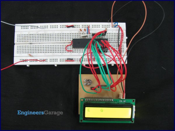
Parts used in the LCD interfacing with PIC16F84A:
- PIC16F84A microcontroller
- 16x2 LCD with HD44780U controller (eg JHD162A)
- Connecting wires
- Power supply for PIC and LCD
- Proteus software (for simulation)
- MPLAB IDE
- HI-TECH C compiler
This post provides the LCD[1] interfacing code in 4bit mode using PIC16F84A microcontroller. This code is written in C language using MPLAB with HI-TECH C compiler. You can download this code from the ‘Downloads‘ section at the bottom of this page.
It is assumed that you know how to make an LED blink with PIC16F84A microcontroller. If you don’t then please read this page first, before proceeding with this article.
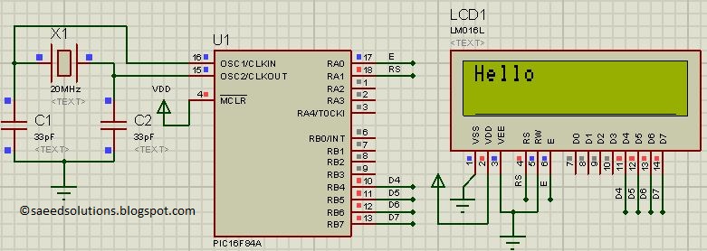
LCD interfacing circuit in 4bit mode with PIC16F84A is shown below.
In the above figure, RA0 pin is being used as Enable pin for LCD. RA1 pin is used as RS pin and RB4 to RB7 pins are being used as Data bus for the LCD. When code starts runing then Hello is displayed on the LCD.
Any 16×2 LCD can be used here which has HD44780U controller in it. For example, JHD162A LCD can be used with this code easily.
Code
The code for the main function is shown below.
In the main function, firstly LCD is initialized using InitLCD() function. After that, “Hello” is written on the LCD screen[2]. In this way using WriteDataToLCD() function, you can write any character on the LCD screen.
InitLCD() function initializes the LCD[3] by giving the initializing commands required to turn the LCD on. This function is shown below.
Downloads
LCD interfacing code in 4bit mode using PIC16F84A was compiled in MPLAB v8.85 with HI-TECH C v9.83 compiler and simulation was made in Proteus v7.10. To download code and Proteus simulation click here.
For more detail: PIC16F84A LCD interfacing code (In 4bit mode) and Proteus simulation
- Which PIC pin is used as the Enable pin for the LCD?
RA0 is used as the Enable pin according to the article. - Which PIC pin is used as the RS pin for the LCD?
RA1 is used as the RS pin as described in the article. - Which PIC pins are used for the 4-bit data bus to the LCD?
RB4 to RB7 are used as the data bus pins for 4-bit mode. - What LCD controller is required for compatibility with the provided code?
The code requires an LCD that has the HD44780U controller. - How is text written to the LCD in this project?
Text is written using the WriteDataToLCD() function after initialization. - How is the LCD initialized in the code?
The InitLCD() function sends the required initializing commands to turn the LCD on. - What development tools were used to compile the code?
The code was compiled in MPLAB v8.85 with the HI-TECH C v9.83 compiler. - In what software was the simulation performed?
Simulation was made in Proteus v7.10.