
Summary of How to display custom characters on LCD using PIC16F84A
This post explains creating custom characters on HD44780U-based LCDs (e.g., 16x2) by writing patterns into the LCD CGRAM and displaying them via a PIC16F84A. It shows wiring (PORTB data bus, RA1=RS, RA0=E), a 20 MHz crystal, how to map 5x8 dot patterns to byte values, and provides InitLCD() code plus downloadable PIC C code and Proteus simulation.
Parts used in the Custom character display on LCD project:
- PIC16F84A microcontroller
- 16x2 or 20x2 LCD with HD44780U controller
- Crystal (20 MHz used, any 0–20 MHz acceptable)
- PORTB connection wires (data bus)
- RA1 connection wire for RS
- RA0 connection wire for E
- Power supply for microcontroller and LCD
- Proteus simulation files (for virtual testing)
- MPLAB v8.85 and HI-TECH C v9.83 compiled code (source files)
This post explains the idea of creating custom characters on any LCD ( e-g on 16×2 LCD ) which has HD44780U controller in it. Almost all 16×2 or 20×2 LCDs have HD44780U controller in them[1]. This controller provides the functionality of CGRAM ( Character Generator RAM ). We can write character patterns on this RAM and then they can be easily displayed on the LCD. The code for custom character generation using PIC16F84A microcontroller and Proteus simulation can be downloaded from the ‘Downloads‘ section at the bottom of this page.
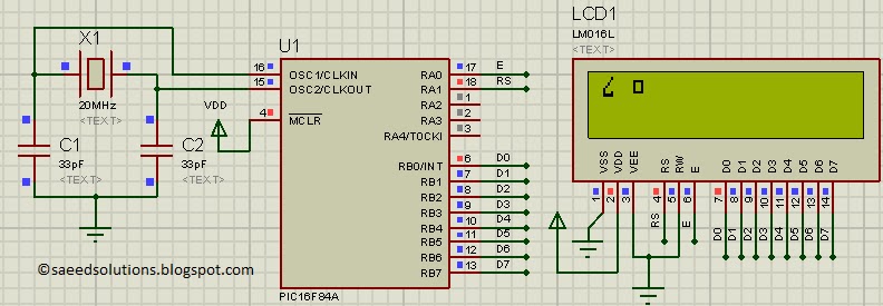
If you don’t know how to interface LCD with PIC16F84A in 8bit mode, then you should read this post first. The required circuit for displaying custom characters on LCD is shown below.
PORTB is being used as data bus for the LCD. Also, RA1 pin is used as RS (Register Select for LCD) and RA0 pin is used as E (Enable pin for LCD).
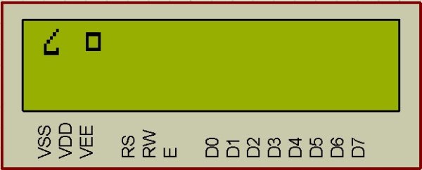
A crystal of 20 MHz is used here. You can use any crystal value from 0 to 20MHz in this circuit. Close-up picture of the LCD is shown below.
Figure 2 shows the custom characters displayed on the LCD by running the code.
How to generate custom character ?
I am going to explain custom character generation using an example. In the figure 2, first character displayed on the LCD is named ‘Curvy Object’ in the code. To generate this character, First make a box of 8 by 5 dots. Then fill the dots required to make the custom character you want to display. Following figure explains this concept.
After filling the dots, find out the value of each line. For example, ( in the figure 3 for ‘Curvy Object’ creation ) first line has a value of 0x01, because only first dot ( at 20 position ) needs to be displayed. Then second line has a value of 0x02, because only one dot at 21 position needs to be displayed. Similarly, third line has a value of 0x04, fourth line has a value of 0x08 and fifth line has a value of 0x10. Sixth line has the two dots to be displayed, hence 0x10 + 0x01 = 0x11 is it’s value. Seventh line has all the dots to be displayed, which corresponds to a value of 0x10 + 0x08 + 0x04 + 0x02 + 0x01 = 0x1F. Eight line has no dots to be displayed, so it has a value of zero. After finding out these values make an array of these values as shown in the figure 3. This array named ‘CurvyObject’, which has 8 bytes of data will be transmitted to the CGRAM of LCD.
Code
The code for the InitLCD() function is shown below[3]. This function is used to initialize the LCD properly with the custom characters.
Downloads
Custom character display on LCD code for PIC16F84A was compiled in MPLAB v8.85 with HI-TECH C v9.83 compiler and simulation was made in Proteus v7.10. To download code and Proteus simulation click here.
For more detail: How to display custom characters on LCD using PIC16F84A
- How do you create custom characters on an HD44780U LCD?
Write 5x8 dot patterns as byte values into the LCD CGRAM and then display them. - Can a PIC16F84A drive custom characters on a 16x2 LCD?
Yes, the post demonstrates using PIC16F84A to write custom characters to CGRAM and display them. - What pins are used to interface the LCD in the example?
PORTB is used as the data bus, RA1 is RS, and RA0 is E. - How do you convert a 5x8 dot line to a byte value?
Assign each column a bit value (1,2,4,8,16) and sum bits for filled dots to get the byte. - What initialization function is provided for the LCD?
The post shows the InitLCD() function used to initialize the LCD for custom characters. - What software and tools were used for code and simulation?
Code was compiled in MPLAB v8.85 with HI-TECH C v9.83 and simulated in Proteus v7.10. - Is a 20 MHz crystal required?
No, the example uses 20 MHz but any crystal from 0 to 20 MHz can be used. - Where can I get the example code and simulation?
The code and Proteus simulation are available for download from the Downloads section referenced in the post.
