Summary of PIC16F628 4 RGB LED PWM Controller using pic microcontroller
Summary (under 100 words): The author built a daisy-chainable RGB LED controller driven by a PIC16F628 using RS232 serial control. Features include PWM for multiple intensities per color, individual control of multiple RGB LEDs, high-speed updates, addressability, and simple serial commands. A PCB was fabricated (BatchPCB) and an error requiring a pull-up on RA5 was noted and corrected in later revisions. Schematics and board files were provided for others to modify.
Parts used in the PIC16F628 4 RGB LED PWM Controller:
- PIC16F628 microcontroller
- RGB LEDs (4 per controller)
- PWM current-limiting resistors for LED channels
- RS232 serial interface components (level shifting as required)
- Pull-up resistor for RA5 (required fix)
- PCB (BatchPCB fabricated board)
- Power supply (suitable voltage for PIC and LEDs)
- Header pins for daisy-chaining/addressing
- Optional components shown on schematic (decoupling capacitors, crystal not required due to internal oscillator)
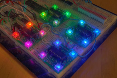
I am a big fan of LEDs. Bright, colorful, flashing LEDs. So, given my affinity for LEDs, I decided to work on a controller that me and a few of my friends could use as an art project/passive information display. I have posted videos from the first prototypes (here and here), but it has been tough to dedicate time to further development given my research, so I thought I would post the information so that anyone can take the design and modify it to their liking!
 Some insipration came from the BlinkM “smart LED” and the ShiftBrite RGB LED Module, but I was interested in using RS232 serial control. Therefore, I chose one of my favorite simple-to-use microcontrollers, the PIC16F628. The advantages include the built-in 4MHz oscillator, hardware USART, and ease of reprogramming. A couple of features I had in mind during the design:
- Multiple intensities for each color (using PWM)
- Multiple individually controllable RGB LEDs
- High-speed update rate
- Daisy-chainable and addressable
- Simple serial control
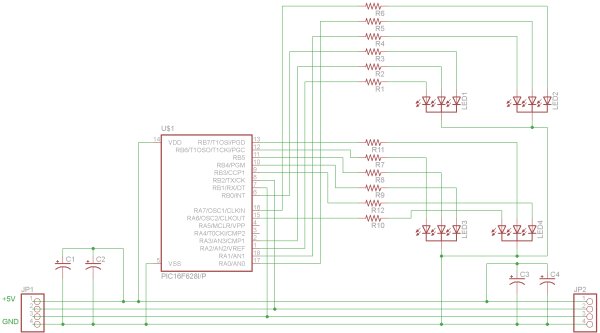
Schematic
Here is the full schematic for the driver. I chose to use a PIC16F628 as the microcontroller because it is cheap, has a internal oscillator (4 MHz) and an internal USART. NOTE: There is an error in this schematic and a pull-up resistor on RA5 (pin 4 in the schematic) is necessary. See the bottom of the post for an updated schematic and board.
 Board
Board
I decided I would try getting a PCB printed for the first time, so I got boards created at BatchPCB.com for $5 each. The total for 4 boards shipped was $32.36 (4 x $5 for the boards and $12.36 for shipping and handling). They took a long time to arrive, but the quality was well worth the wait. NOTE: There is an error on the first revision of the board and a pull-up resistor on RA5 (pin 4 in the schematic above) is necessary. You can see how I compensated for the mistake in the second picture below (look on the back of the upper-left board). This will be corrected in future revisions. See the bottom of the post for an updated schematic and board.
For more detail: PIC16F628 4 RGB LED PWM Controller
- What microcontroller is used in the project?
The project uses a PIC16F628 microcontroller with a built-in 4 MHz oscillator and hardware USART. - How are multiple intensities for each color achieved?
Multiple intensities are achieved using PWM (pulse-width modulation) on each color channel. - Can multiple RGB LEDs be individually controlled?
Yes, the design supports multiple individually controllable RGB LEDs (four per controller). - Is the controller daisy-chainable and addressable?
Yes, the controller is designed to be daisy-chainable and addressable. - What serial protocol is used to control the LEDs?
The controller uses RS232 serial control via the PIC16F628 USART. - Was a PCB used and where was it fabricated?
Yes, PCBs were fabricated through BatchPCB.com. - Were there any known errors in the initial design?
Yes, the initial schematic and first board revision omitted a required pull-up resistor on RA5; the author added a fix and corrected it in later revisions. - Does the design require an external crystal for the PIC?
No, the PIC16F628 internal 4 MHz oscillator is used, so an external crystal is not required.