Summary of LCD interface with Microcontroller PIC: Beginner’s guide using pic microcontoller
This article explains interfacing a 16×2 LCD module with a PIC microcontroller using Mikro C. It details the functions of control lines (EN, RS, RW) and data bus (DB0-DB7), emphasizing a 4-bit mode connection where DB0-DB3 are grounded. The guide covers wiring specific pins to Port C (RC2-RC7) and initializing bits for the library.
Parts used in the PIC Microcontroller LCD Interface:
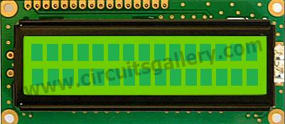
- 16×2 LCD display module
- PIC microcontroller
- Mikro C compiler
- Data bus lines (DB0 to DB7)
- Enable pin (EN)
- Register Select pin (RS)
- Read/Write pin (RW)
- LED back light pins (LED+ and LED-)
How to interface LCD (Liquid Crystal Display) display module to PIC microcontroller? LCD is a passive component, that is it does not make any light but just modifies the light passing through it for alphanumeric displays. LCD is exclusively manufactured to be used with microcontrollers, which means that it cannot be triggered by usual IC circuits. This embedded program shows how to connect PIC to LCD display module with microcontroller programming.Here 16×2 LCD interfaces with the PIC microcontroller. This type of LCD screen can display 2 lines with 16 characters each. Every character consists of 5×8 or 5×11 dot matrix. It can display all the letters of alphabet, Greek alphabet, mathematical symbols, punctuation marks etc. It is also likely to display symbols prepared by the user. Other positive features consist of automatic message shift (left and right), cursor appearance, LED back light etc. Interfacing LCD to microcontroller is quite simple program for beginners and easy to understand.
 EN – Enable:
This control line is used to inform the LCD that you are sending in data. To send data to the LCD, put data on the data bus, then make EN high (1) and wait a little bit and end by bringing EN to low (0) again.
RS – Register Select:
When RS is low (0), the information in the DB0 to DB7 pins are to be considered as an instruction (command- such as Clear screen, Display set, etc.). When RS is high (1), the information in the DB0 to DB7 pins are to be considered valid text data to print on the LCD screen. For example, to display the letter “i” on the screen you should set RS= high.
RW – Read/Write:
When RW is low (0), the information on the data bus is written to the LCD module.
DB0 to DB7:
Data bus lines of LCD display.
LED+, LED-:
Used for enabling back light on the screen. If you don’t want the back light you can leave it unconnected.
Basic connection circuit diagram of LCD interfacing with PIC
- We can interface LCD to PIC in 4 bit mode
- So D0, D1, D2, D3 of LCD display are grounded since connection is 4 bit mode and the D4, D5, D6, D7 are connected to Port C higher bits RC4, RC5, RC6, RC7 respectively.
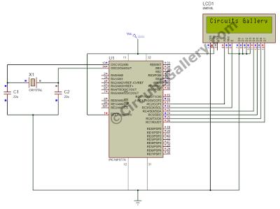
- RS pin of LCD module connected to RC2 (PORTC.F2), this will decide whether the LCD inputs are data input or instruction input. In the case of Mikro C compiler we doesn’t bother about this pin, only we need to initialize it as sbit LCD_RS at RC2_bit; rest all the operation done by LCD Library function inside Mikro C.
- RW (Read/Write) pin grounded because we are writing to LCD display. (For writing RW=0; For reading RW=1;)
- Enable (EN) pin connected to RC3 (PORTC.F3), a HIGH to LOW transition of this pin needed in order to transfer data or command from PIC to LCD module. As I said above, Mikro C LCD library function will do the job for us. Just initialize the bit as sbit LCD_EN at RC3_bit;
Fo more detail: LCD interface with Microcontroller PIC: Beginner’s guide
- What type of LCD is exclusively manufactured for use with microcontrollers?
LCD is exclusively manufactured to be used with microcontrollers and cannot be triggered by usual IC circuits. - How many lines and characters can a 16×2 LCD display?
This LCD screen can display 2 lines with 16 characters each. - Can you display user-prepared symbols on this LCD?
Yes, it is likely to display symbols prepared by the user. - How do you set the RS pin to print text data?
To display valid text data, set RS high (1). - What value should the RW pin have when writing to the LCD?
The RW pin must be low (0) when writing information to the LCD module. - Why are D0 through D3 grounded in this project?
D0 through D3 are grounded because the connection is configured in 4-bit mode. - Which PIC port pins connect to the RS and EN pins?
RS connects to RC2 and EN connects to RC3. - Does the Mikro C compiler require manual handling of the RS and EN pins?
No, only initialize them as sbit; the LCD Library function handles the rest.