Summary of lc meter capacimeter inductimeter circuit pic 16f84 auto range lcmeter
This article details a high-precision LC meter project using a PIC 16F84 or 16F628 microcontroller and an LCD display. Designed by Phil Rice, the device measures capacitance from 0 to 800nF and inductance up to 10mH with ±1% precision. It utilizes a parallel LC oscillator circuit with an LM311 comparator and a relay for auto-ranging calibration against a precise 1000pF capacitor. The system features zeroing capabilities for residual values and supports various LCD configurations.
Parts used in the LC Meter Project:
- PIC 16F84 or PIC 16F628 microcontroller
- LCD display (Hitachi 16x1, 16x2, or 8x2)
- LM311 comparator
- Relay
- 1000 pF ±1% polystyrene calibration capacitor (Ccal)
- Polystyrene or NPO capacitor for C2
- 82 µH RF choke or toroidal coil (85 turns AWG 30 on iron powder core)
- 7805 voltage regulator (TO-220 package)
- Potentiometer for contrast adjustment
- Resistors (5% or 1% tolerance)
The good and high precision capacitor meter (Capacimeter) inductor meter (inductimeter) auto range lc meter for pic 16f84 or pic 16f628 and display lcd by phill rice
Construction of an apparel that allows measure inductors (Inductimeter) and capacitors (Capacimeter), knower like LC meter, using PIC (16f84 or 16f628) and display marries in LCD.
Translated of the excellent project inductor and capacitor meter ( lcmeter ) of the Phil Rice
VK3BHR.
schematic
Image gallery
Specifications for the lc meter with pic
The measure reach: is from 0 to 800nF to capacitance and 0 to 10mH goes inductance.
Precision: is of ± 1%
Reading: 0 to 1000pF (1nF) in pF 1nF to 800nF in nF auto range (it range automatic)
Resolution: is of ± 0.1 pF and ± 10nH. Good to have in the supported.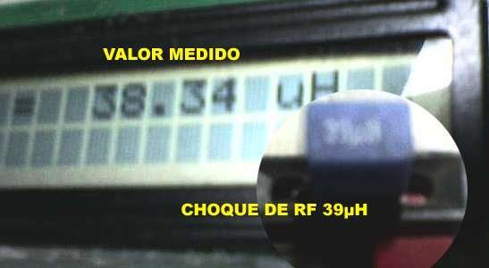
As works the lc meter with pic 16f84 or 16f628
THE PROJECT OF THE OSCILLATOR CAME FROM THE PAGE OF LC meter OF
AADE
It use the comparator LM311 with positive feedback
working the an oscillator parallel LC with digital exit. L is the shock of 82 µH and C it is the capacitor of 1000 pF. The frequency therefore it is f1 = 550 kHz. The capacitor of value precise, (CCal) 1000 pF ±1%, is linked in parallel C through the relay. The new total capacity is 1000 + 1000(Ccal) = 2000 pF, and the new frequency is f2 = 394 kHz. It is not important that those frequencies plows exact, the one that imports is the relationship among them, that flows of the capacitor of precision of 1000 pF. The two frequencies plows measured by PIC, during the solemnity-calibration. The important is that if the capacitor of 1000 pF (Ccal) it is necessary, then only the value of L exists (the shock of 82 µH) and the value of C (the capacitor of 1000 pF) that can determines those two frequencies, not importing your absolute values exactly. it GAVE WAY PIC ” it DISCOVERS ” THE TRUE AND CORRECT VALUE OF THE SHOCK AND OF THE CAPACITOR OF 1000 PF, AND TENDS THAT IT CAN MEASURE THE CAPACITOR OR AN EXTERNAL INDUCTOR. The inductor in test is placed in series with the shock. The capacitor in test is placed in parallel to the of 1000 pF
To the accomplish the solemnity-calibration, the inductances and capacitances sponge of the spinning it plows absorbed in the calculation accomplished by PIC. The key CH3 makes ” to zero ” the suitable value in the display. it gave way, only the capacity or additional inductance of the component to be measured plows shown in the display.
Assembly for the digital inductimeter and capacimeter
The tolerance of the apparel depends on the capacitor Ccal 1000pF, that should be made of polystyrene (styroflex “) with tolerance of less for the 1%. Oh you ask, where I get the capacitor with that tolerance, easy, make the capacitors association to get the wanted capacity, goes that to it uses the borrowed commercial Capacimeter of it adds amigo selects the capacitors to be used in the circuit. IN MY PROTOTYPE I USED ONE WITH TOLERANCE OF 1% GOTTEN IN THE SCRAP, RARE THING. C2 (Cmed) doesn’t need to be I need, just it is necessary thermal stability. Therefore uses one of polystyrene, if it will it uses potter it you use NPO.
It goes the inductor I used of begin the shock of RF 82µH, however the measures were not firm, then I used the coil toroidal with 85 you exhale of thread 30 coiled AWG in nucleus of powder of iron.
Display lcd for the lcmeters project
It display can be any one pattern Hitachi 16×1, 16×2 or 8×2, If it will uses one that you have backlight, it should have attention goes the consumption of energy. That it will be very larger, being recommended to uses to 7805 to-220.
In my prototype, I used PIC 16f627 from block telephone abandoned and the display in an apparel of fax destroyed. Live la scrap.
The resistors of the circuit can be of tolerance of 5%, adds demanding ones they it lives it uses with tolerance of 1%.
how to program the pic for the circuit lcmeter
To program PIC is easy you need the closes recorder and of the program. The one that I used was the grabber PROPIC2 of the magazine Mecatronica fácil (portuguese) from saber electronic. and the program is IC-PROG.
How to test the circuit lcmeter
All weld the components in the plate, without PIC, measure the tension of the regulator to verify 5 volts ± 25%. Everything right terrifies the pin 18 of the socket of the PIC and verify the operation of the relay (you should hear the relay being worked). Place Display it ties the circuit and adjust the potentiometer goes the best contrast. Already place the PIC engraving with the program and if everything certain you have Lc to digital put. In marries it doesn’t work it inspects every circuit, display, PIC ,Chaves, spinning, etc.
It goes it presses zero. PIC will count the cycles of the oscillator goes 0.1 seconds and it will exhibit the result. Com the inductor of 82µH and the capacitor of 1000pF in the circuit (without any external component, any calibration capacitor) the oscillator will run the approximately 550KHz, and the display it will show about 55000.
If the frequency goes very high (above 655.350KHz) the display will show reach out. If the oscillator i not working it will be shown 0 in the display.
It goes better precision the frequency should be of 10 a 15% inferior of 655KHz. You can adjust the coil to get.
One according to jumper connects the calibration capacitor Ccal, the frequency now will be of 394KHz.
The third Jumper in the pin 10 of the PIC, allows to select the display of 8 x 2, the result it will be shown in two lines.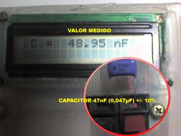
To measure Inductor l meter
Select L in the function key the display it will show ” reach ” out, that reason doesn’t have any connected inductor. Place the measure terminals in shorts and press zero. Now it i only to place the inductor and to read the result.
To Measure capacitor c meter
Select C in the function key the display it will show adds pF, it is the capacity residual (it sponges) of the spinning. Work the key “zero” goes the brief instant. The display now indicates 0 pF. Now it is only to place the capacitor to measure in the terminals and to read the result in the display.
For more detail: lc meter capacimeter inductimeter circuit pic 16f84 auto range lcmeter
- What components are required to build the LC meter?
The project requires a PIC 16F84 or 16F628, an LCD display, an LM311 comparator, a relay, specific capacitors, an inductor, a 7805 regulator, and resistors. - How does the calibration process work?
The PIC measures two frequencies created by connecting a precise 1000pF calibration capacitor via a relay to determine the true values of the inductor and capacitor. - Can I use any type of capacitor for the calibration component?
No, the calibration capacitor must be made of polystyrene with a tolerance of less than 1% to ensure accuracy. - What is the measurement range for capacitance?
The meter measures capacitance from 0 to 800nF with an auto-range feature showing readings in pF or nF. - How do I test if the circuit is working before inserting the PIC?
You should measure the regulator voltage to verify 5 volts, check pin 18 of the socket, and listen for the relay operation. - What happens if the oscillator frequency exceeds 655.350KHz?
If the frequency goes very high above this limit, the display will show reach out. - How can I select a different display format?
A third jumper connected to pin 10 of the PIC allows you to select an 8x2 display where results appear on two lines. - What is the best way to prepare the inductor for testing?
For better stability, use a toroidal coil with 85 turns of AWG 30 wire on an iron powder core instead of a standard RF choke.