Summary of Dual Motor L298 H-Bridge Motor Control
This article describes a Dual Motor L298 H-Bridge Control project capable of driving two DC motors or stepper motors. Designed around the ST L298 dual H-Bridge chip, the circuit features current sense resistors, external diode bridge protection, and screw terminal connectors for easy wiring. It supports motor supply voltages from 7 to 46 VDC with an output drive of up to 2 A per channel, including heat-sinking and LED indicators for status monitoring.
Parts used in the Dual Motor L298 H-Bridge Control:
- Dual H-Bridge L298 chip
- Current sense resistors
- External diode bridge
- Heat-sink
- Power-On LED indicator
- Screw terminal connector
- PCB board
Dual Motor L298 H-Bridge Control project can control two DC motors connected to it. The circuit has been designed around popular dual H-Bridge L298 from ST. This circuit has current sense resistors for both H-bridges to provide voltage which enables this board to use in stepper motor applications.
Specifications
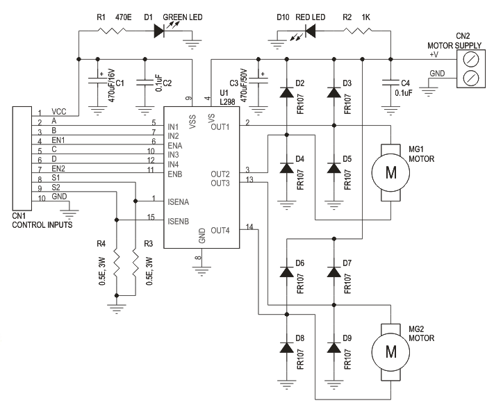
Motor supply : 7 to 46 VDC
Control Logic Supply : Standard TTL logic level
Output DC drive to motor : up to 2 A each
Current Sense Output available
Enable and direction control pins available
External diode bridge for protection
Heat-sink for IC
Power-On LED indicator
Screw terminal connector for easy input supply (PWR) / output (Motor) connection
Four mounting holes of 3.2 mm each
PCB dimensions 61 mm x 63 mm
For more detail: Dual Motor L298 H-Bridge Motor Control
- What is the primary function of this project?
The project controls two DC motors connected to it using a dual H-Bridge design. - Can this circuit be used for stepper motor applications?
Yes, the inclusion of current sense resistors enables the board to be used in stepper motor applications. - What is the required motor supply voltage range?
The motor supply must be between 7 to 46 VDC. - How much current can each motor output drive?
The output DC drive to the motor is up to 2 A for each channel. - Does the circuit include protection against electrical issues?
Yes, it features an external diode bridge for protection. - How are the input and output connections made?
It uses screw terminal connectors for easy input supply and output motor connections. - What logic level does the control supply require?
The control logic supply requires standard TTL logic level.