Switching DC-to-DC voltage converters (“regulators”) comprise two elements: A controller and a power stage. The power stage incorporates the switching elements and converts the input voltage to the desired output. The controller supervises the switching operation to regulate the output voltage. The two are linked by a feedback loop that compares the actual output voltage with the desired output to derive the error voltage.
The controller is key to the stability and precision of the power supply, and virtually every design uses a pulse-width modulation (PWM) technique for regulation. There are two main methods of generating the PWM signal: Voltage-mode control and current-mode control. Voltage-mode control came first, but its disadvantages––such as slow response to load variations and loop gain that varied with input voltage––encouraged engineers to develop the alternative current-based method.
Today, engineers can select from a wide range of power modules using either control technique. These products incorporate technology to overcome the major deficiencies of the previous generation.
This article describes voltage- and current-mode control technique for PWM-signal generation in switching-voltage regulators and explains where each application is best suited.
Voltage-mode control
Designers tasked with building a power supply can either build a unit from discrete components (see the TechZone article “DC/DC Voltage Regulators: How to Choose Between Discrete and Modular Design”), separate controller and power components, or power supply modules that integrate both elements into a single chip.
But whichever design technique is employed, there is a high probability that regulation will employ a PWM technique of (typically) a fixed frequency. (A constant-switching frequency is desirable because it limits electromagnetic interference (EMI) generated by the power supply.)
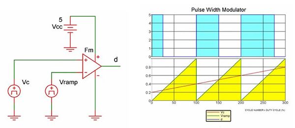
In a voltage-mode controlled regulator, the PWM signal is generated by applying a control voltage (VC) to one comparator input and a sawtooth voltage (Vramp) (or “PWM ramp”) of fixed frequency, generated by the clock, to the other (Figure 1).
The duty cycle of the PWM signal is proportional to the control voltage and determines the percentage of the time that the switching element conducts and therefore, in turn, the output voltage (see the TechZone article “Using PFM to Improve Switching DC/DC Regulator Efficiency at Low Loads”). The control voltage is derived from the difference between the actual-output voltage and the desired-output voltage (or reference voltage).
The modulator gain Fm is defined as the change in control voltage that causes the duty cycle to go from 0 to 100 percent (Fm = d/VC = 1/Vramp).1
Figure 2 shows the building blocks of a typical switching regulator. The power stage comprises a switch, diode, inductor, transformer (for isolated designs), and input/output capacitors. This stage converts the input voltage (VIN) into the output voltage (VO). The voltage regulator’s control section comprises an error amplifier with the reference voltage (equal to the desired output) on one input and the output from a voltage divider on the other. The voltage divider is fed from a feedback trace from the output. The output from the error amplifier provides the control voltage (VC or “error voltage”) that forms one input to the PWM comparator.2
For more detail: Voltage- and Current-Mode Control for PWM Signal Generation in DC-to-DC Switching Regulators

