
Summary of Latest Microcontroller Based Electronic Project Circuits in 2014
This article lists simple microcontroller-based projects—including a biometric fingerprint security system, GSM-based highway vehicle monitoring, RFID electronic toll plaza, and a quiz buzzer—describing their purpose, hardware components, circuit connections, and brief operation explanations for each.
Parts used in the Microcontroller-Based Electronic Project Circuits:
- Fingerprint sensor
- Microcontroller (8051 family referenced)
- LCD display
- Buzzer
- Keyboard
- Resistors
- Capacitors
- Transistors
- Relay and relay driver IC
- Step-down transformer
- Rectifiers
- GSM modem
- GPS receiver
- Max-232
- Flash memory
- Crystal
- RFID sensor
- Pull-up resistors
- Switches / push-button switches
- Seven-segment display
- Speaker
A microcontroller is a small computer on a single integrated chip that is programmed to control the devices. Most of the embedded-based projects require knowledge about programming the microcontroller. Once students get an idea about the circuit, schematics and their operations, it becomes really easy to program a microcontroller.
This article provides a list of simple microcontroller-based electronic project circuits.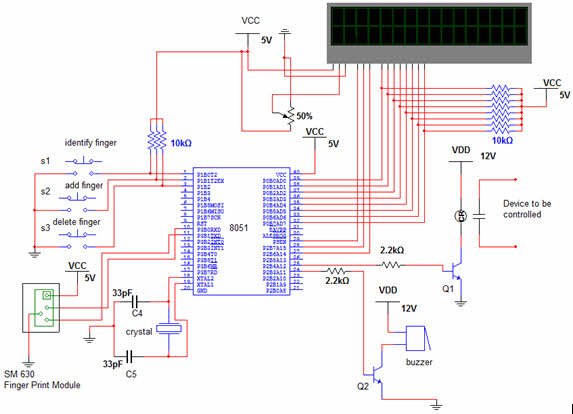
1. Biometric Fingerprint Based Security System
A biometric security system can recognize a person based on their fingerprint and uses a fingerprint scanner for the same. Traditional security systems can be inconvenient and time consuming and sometimes even error prone. The biometric-security systems are most secure and accurate than the traditional password security systems, and can be used at many places like industries, offices, collages, etc.
The process involves taking the image of the fingerprint and processing the stored image to get the data, and then comparing this data with the existing information in the database.
Hardware Components
- Fingerprint sensor
- Microcontroller
- LCD display
- Buzzer
- Keyboard
- Resistors
- Capacitors
- Transistors
Circuit Connections
- This electronic project circuit is constructed with a fingerprint module, an LCD, a Buzzer, a relay and switches.
- The fingerprint scanner is a 4-pin device with VCC, TX, RX and Ground pins. It is connected to pins 10, 11, 16 of the microcontroller.
- The LCD is an output device interfaced to the PORT0 pins of the microcontroller.
- A buzzer is connected to the pin number 24 of the microcontroller through a transistor.
- The switches are input devices interfaced to input pins: 1, 2, and 3 of the microcontroller. The relay is connected to the pin 25 of the microcontroller through a relay driver IC.
Circuit Explanation
- The 230v AC voltage is converted into a 12v AC with the help of a step-down transformer and the 12v AC is converted to a 12v DC with the help of the rectifiers to drive the circuit.
- The microcontroller develops the output logic signals and the load (DC motor) is switched on and off.
- The fingerprint scanner gives high and low-logic signals at the input of the microcontroller. The microcontroller is programmed to transfer the data to be displayed on the microcontroller, and also generates the corresponding output signal.
- When the microcontroller output pin goes high, the transistor conducts, and the relay coil is energized. This drives the DC motor to rotation in the forward and backward direction.
2. GSM-based Highway Vehicle Monitoring System
The vehicle monitoring system is designed for tracking the location or geographical position of any vehicle on the highways by using GPS navigation system and GSM features.The GSM modem and GPS receiver are both interfaced to 8051 microcontroller. The GPS modem gets the longitude and latitude data, indicating the position of the vehicle, and the GSM modem sends this data to the concerned authority.
Upon receiving a request from a user to the modem, the system sends the information about the position of the vehicle in terms of longitude and latitude.
Hardware Components
- LCD
- GSM Modem
- GPS receiver
- Max-232
- Microcontroller 8051 family
- Flash Memory
- Resistors
- Capacitors
- Crystal
Circuit Connections
- The transmitter (Tx) and receiver (Rx) pins of the GSM modem are connected to the microcontroller port pins 10 and 11, respectively.
- LCD display is interfaced to the port 0 pins of the microcontroller.
- The flash device is connected to the 24 and 25 pins of the microcontroller.
Circuit Explanation
- The GPS receiver of the circuit receives the longitude and latitude information from the satellites.
- The microcontroller receives the location information from the GPS receiver.
- The microcontroller is programmed in order to send the location information to the GSM modem.
- The GSM modem transmits this information to the concerned authority.
3. RFID-based Electronic Toll Plaza System
These days electronic toll plaza system is fast replacing the traditional toll plaza system that involves manual force for toll collection. The advanced system consists of a RFID system that stores the details about the payment and vehicles.
The user ID card, which is also an RFID tag is scanned through the reader and the information present in the card, is accordingly processed, i.e., the toll amount is deducted from the account of the user
Hardware Components
- LCD display
- Max-232
- Resistors
- Capacitors
- Microcontroller
- RFID sensor
Circuit Connections
- The LCD is interfaced with the help of the pull-up resistors at PORT0 pins of the microcontroller 8051.
- The RFID sensor is interfaced to the pins 10 and 11 of the microcontroller through a max-232 dev.
- The crystal circuit is connected to the pins 18 and 19 of the microcontroller.
Circuit Explanation
- The RFID tag consisting of the user information and account details is swiped on the RFID reader.
- The RFID reader receives the information from the tag in the form of a 12-bit serial data.
- The serial data is fed to the microcontroller through the Max-232.
- The microcontroller is programmed in order to process the received data and display the processed result on the LCD display.

4. Quiz Buzzer Using Microcontroller
Quiz Buzzer systems are commonly used in schools and colleges during competitions. The process involves giving priority to the person who presses the buzzer at the earliest. However, the problem arises with the conventional buzzer systems if the buttons are pressed simultaneously by two or more persons. In such cases, it is difficult to make a choice, and sometimes the decision can be biased with the human intervention.
The quiz-buzzer system proposed here consists of 8 switches corresponding to eight teams. The output is displayed on the 7-segment display. The buzzer is also devised to give an alarm sound for an infinitesimally small duration of time.
Hardware Components
- Switches
- Seven-segment display
- Microcontroller
- Speaker
- Resistors
- Capacitors
- Crystal
Circuit Connections
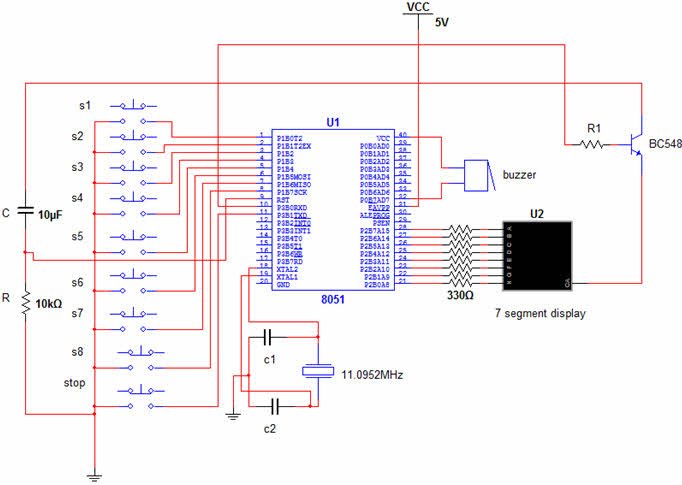
- The 8-push button switches are connected to the PORT1 of the microcontroller.
- The speaker is connected to the pin 32 of the microcontroller.
- The seven-segment display is connected to the PORT2 pins of the microcontroller.
- The 11.0952 MHz crystal is interfaced to the pins 18 and 19 of the microcontroller.
Circuit Explanation
- When any of the switch or any two switches are pressed, the microcontroller input pins receive a low-logic signal.
- The microcontroller is programmed in order to display the corresponding number of the switch on the 7-segment display, based on the timer values.
- At the same time, microcontroller is also programmed in order to give signals to ring the buzzer.
For more detail: Latest Microcontroller Based Electronic Project Circuits in 2014
- What is a biometric fingerprint based security system used for?
It recognizes a person based on their fingerprint to provide secure access, replacing traditional password systems. - How is the fingerprint scanner connected to the microcontroller?
The fingerprint scanner is a 4-pin device (VCC, TX, RX, Ground) connected to pins 10, 11, and 16 of the microcontroller. - Can the GSM-based highway vehicle monitoring system send vehicle location remotely?
Yes, the system uses a GPS receiver to get longitude and latitude and a GSM modem to transmit that information to the concerned authority. - How are the GSM modem Tx and Rx pins connected?
The GSM modem Tx and Rx pins are connected to microcontroller port pins 10 and 11 respectively. - What role does the Max-232 play in the RFID-based toll plaza system?
Max-232 interfaces the RFID sensor serial data to the microcontroller by converting signal levels. - How does the quiz buzzer system determine which team pressed first?
Eight push-button switches are connected to PORT1; the microcontroller detects low-logic input and displays the corresponding team number on the seven-segment display based on timer values. - Where is the seven-segment display connected in the quiz buzzer circuit?
The seven-segment display is connected to the PORT2 pins of the microcontroller. - How is the LCD interfaced in multiple projects?
The LCD is interfaced to PORT0 pins of the microcontroller, often using pull-up resistors as noted for the RFID project. - How is the relay used in the fingerprint security project activated?
The microcontroller output drives a transistor that energizes the relay coil, which switches the DC motor on or off.
