Summary of Interrupt Routine in Assembly Language Using 8-bit PIC
This article provides a beginner's guide to programming external interrupts in Assembly for PIC microcontrollers. It details building a simple circuit using a PIC 16F870 or 16F84A, connecting LEDs and an oscillator, and writing code to toggle LED states upon receiving an external impulse on the RB0 pin. The tutorial explains configuring ports, enabling global and external interrupts via the INTCON register, and implementing the interrupt service routine.
Parts used in the Experimental Basic Circuit:
- 8-bit/28-pin PIC 16F870 microcontroller
- PIC 16F84A microcontroller (recommended alternative)
- Two 1/4W LEDs
- One 20MHz Crystal XT Oscillator
- Three 330 Ohm Resistors
Hello reader. This is one of the most basic and important instruction ever made for Microcontrollers low level programming. Talking about the external interrupts routine in Assembly Language for PIC. Today I’ll present a blueprint for the development of an experimental basic circuit and show you the coding to learn how to use this simple but usefull routine.
Firstable, i’ll assume you all know basics about PIC, Assembly and the whole working enviroment (MPLAB, PicKit 2 v-2.55). If you dont, just ask.
Step 1: Circuit Schems and Materials.
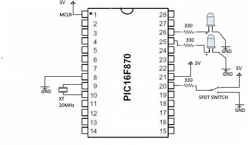
Circuit is pretty simple: I use a 8bit/28pin PIC 16F870 but i recommend 16F84A because its unexpensive and enough to learners. Also, i use 2x LED’s 1/4W connected to RB5 & RB6, 1x 20MHz Crystal XT Oscillator and 3x 330 OHM’s Resistors: two to control the LED’s current and one for the external impulse.
Step 2: Assembly Coding
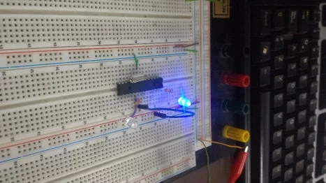
Next step: The coding thing. Some people consider a good practice to perform a “Blink” to test the PIC Outputs. Asuming that everything is ok and we’re having an stable 5VDC source, let’s “Burn” that microcontroller with the code attached.
<p>list p=16F870<br>include	"p16f870.inc"</p><p>		ORG		00h
 		GOTO		INICIO</p><p>		ORG		04h			;Comienzo de los registros para almacenar Instrucciones

		BCF		PORTB,4
		BSF		PORTB,5
		BCF		INTCON,1
		RETFIE</p><p>		ORG		30h			;Final de los registros para almacenar Instrucciones</p><p>INICIO	BSF		STATUS,5		;Cambio de Banco a 1
		BCF		STATUS,6		;Cambio de Banco a 1	</p><p>		BCF		TRISB,5			;RB5 Salida
		BCF		TRISB,4			;RB4 Salida
		BSF		TRISB,0			;RB0 Entrada
		BCF		STATUS,5		;Devuelve al Banco 0</p><p>		BSF		INTCON,7		;Habilita las interrupciones
		BSF		INTCON,4		;Habilita Interrupciones externas RB0/INT </p><p>		BCF		PORTB,5			; LED APAGADO
		BSF		PORTB,4			; LED ENCENDIDO</p><p>ARRIBA	BTFSS		PORTB,5
		nop
		GOTO		ARRIBA

		END</p>
This interruption routine works with and external high impulse set on RB0 pin. When the INT its performed, both of the LED’s are going to change their status.
Let’s breakdown the code:
Configuration Routine just setup the ports we’re going to use as Inputs and Outputs
		BSF		STATUS,5		;Bank 1º						BCF		STATUS,6		;Bank 1
		BCF		TRISB,5			;RB5 Output
		BCF		TRISB,4			;RB4 Output
		BSF		TRISB,0			;RB0 Input
		BCF		STATUS,5		;Bank 0
Then enable the INTCON Register and set the portb status.
		BSF		INTCON,7		;Enable Global Interrupt Routines
		BSF		INTCON,4		;Enable External interrupts RB0/INT			BCF		PORTB,5			; LED OFF						BSF		PORTB,4			; LED ON
Finally the INT routine which change PORTB status and clear the INT External interrupt Flag.
<p>	BCF		PORTB,4<br>	BSF		PORTB,5
	BCF		INTCON,1
	RETFIE</p>
Try it, change it to perform any other action and enjoy!
Attachments
Source: Interrupt Routine in Assembly Language Using 8-bit PIC
- What microcontroller is recommended for learners?
The PIC 16F84A is recommended because it is inexpensive and sufficient for learning. - How do you enable global interrupt routines in the code?
You enable them by setting bit 7 of the INTCON register using the BSF instruction. - Which pin is used for the external impulse input?
The external impulse is set on the RB0 pin, also known as the INT pin. - What happens when the external interrupt occurs?
When the interrupt is performed, both LEDs change their status. - How do you configure RB0 as an input port?
You configure RB0 as an input by setting bit 0 of the TRISB register to 1 using BSF STATUS and TRISB instructions. - What components are connected to RB5 and RB6?
Two 1/4W LEDs are connected to RB5 and RB6. - How many resistors are required for the circuit?
Three 330 Ohm resistors are required: two for controlling LED current and one for the external impulse. - What software environment is assumed for this project?
The text assumes familiarity with MPLAB and PicKit 2 v-2.55.