
Summary of Interfacing LM35 temperature sensor with PIC18F4550 microcontroller
This article details the interfacing of an LM35 temperature sensor with a PIC18F4550 microcontroller using CCS C. It explains the linear voltage-to-temperature relationship (10mV/°C) and provides the necessary circuit connections, hardware components, and conversion formulas to display real-time temperature on a 1602 LCD screen.
Parts used in the Interfacing PIC18F4550 with LM35:
- PIC18F4550 microcontroller
- LM35 temperature sensor
- 1602 LCD screen
- 10K ohm variable resistor
- Breadboard
- 5V voltage source
- Jumper wires
This small topic shows the circuit diagram and CCS C code of the interfacing of LM35 temperature sensor with PIC18F4550 microcontroller.
The LM35 temperature sensor is three pin device (VCC, OUT and GND) with an output voltage linearly related to Centigrade temperature. Since the LM35 output varies with dependent to the temperature we need ADC (Analog-to-Digital Converter) module to measure this voltage. The ADC module converts analog data into digital data.
The LM35 output has linear +10mV/°C scale factor means the following:
If the output voltage = 10mV —> temperature = 1°C
If the output voltage = 100mV —> temperature = 10°C
If the output voltage = 200mV —> temperature = 20°C
If the output voltage = 370mV —> temperature = 37°C
and so on.
LM35 Futures (from datasheet):
- Calibrated Directly in ° Celsius (Centigrade)
- Linear + 10 mV/°C Scale Factor
- 0.5°C Ensured Accuracy (at +25°C)
- Rated for Full −55°C to +150°C Range
- Suitable for Remote Applications
- Low Cost Due to Wafer-Level Trimming
- Operates from 4 to 30 V
- Less than 60-μA Current Drain
- Low Self-Heating, 0.08°C in Still Air
- Nonlinearity Only ±¼°C Typical
- Low Impedance Output, 0.1 Ω for 1 mA Load
Hardware Required:
- PIC18F4550 microcontroller
- LM35 temperature sensor — datasheet
- 1602 LCD screen
- 10K ohm variable resistor
- Breadboard
- 5V voltage source
- Jumper wires
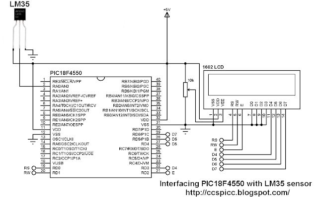
Interfacing PIC18F4550 with LM35 sensor circuit:
The output of the LM35 temperature sensor is connected to analog channel 0 (AN0) of the PIC18F4550 microcontroller.
In this example the MCU uses its internal oscillator and MCLR pin function is disabled.
Interfacing PIC18F4550 with LM35 temperature sensor C code:
The C code below was tested with CCS PIC C compiler version 5.051.
Reading voltage quantity using the ADC gives us a number between 0 and 1023 (10-bit resolution), 0V is represented by 0 and 5V is represented by 1023. Converting back the ADC digital value is easy and we can use the following equation for that conversion:
Voltage (in Volts) = ADC reading * 5 / 1023
Multiplying the previous result by 100 (LM35 scale factor is 10mV/°C = 0.01V/°C) will gives the actual temperature:
Temperature(°C) = ADC reading * 0.489
where 0.489 = 500 / 1023
The complete C code is the one below.
/* Interfacing PIC18F4550 with LM35 analog temperature sensor CCS C code.
   Read LM35 datasheet to understand the code!
   http://ccspicc.blogspot.com/
   [email protected]
*/

//LCD module connections
#define LCD_RS_PIN      PIN_D0
#define LCD_RW_PIN      PIN_D1
#define LCD_ENABLE_PIN  PIN_D2
#define LCD_DATA4       PIN_D3
#define LCD_DATA5       PIN_D4
#define LCD_DATA6       PIN_D5
#define LCD_DATA7       PIN_D6
//End LCD module connections

#include <18F4550.h>
#fuses NOMCLR, INTRC_IO
#device ADC=10
#use delay(clock = 8MHz)
#include <lcd.c>

char temperature[] = " 00.0 C";
unsigned int16 temp;
void main(){
  setup_oscillator(OSC_8MHZ);                    // Set internal oscillator to 8MHz
  setup_adc(ADC_CLOCK_INTERNAL);                 // ADC Module uses its internal oscillator
  setup_adc_ports(AN0);                          // Configure AN0 pin as analog
  set_adc_channel(0);                            // Select channel 0 (AN0)
  lcd_init();                                    // Initialize LCD module
  lcd_putc('\f');                                // Clear LCD
  lcd_gotoxy(3, 1);                              // Go to column 3 row 1
  printf(lcd_putc, "Temperature:");
  temperature[5]  = 223;                         // Put degree symbol (°)
  while(TRUE){
    delay_ms(1000);
    temp = read_adc() * 0.489;                   // Read analog voltage and convert it to degree celsius (0.489 = 500/1023)
    if (temp > 99)
      temperature[0]  = 1 + 48;                  // Put 1 (of hundred)
    else
      temperature[0]  = ' ';                     // Put space
    temperature[1]  = (temp / 10) % 10  + 48;
    temperature[2]  =  temp % 10  + 48;
    lcd_gotoxy(5, 2);                            // Go to column 5 row 2
    printf(lcd_putc, temperature);               // Display LM35 temperature result
  }
}
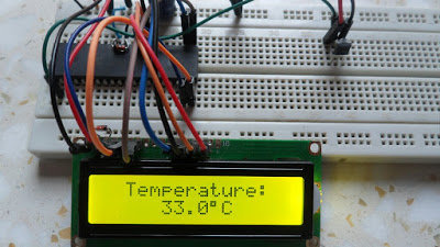
The result

Source: Interfacing LM35 temperature sensor with PIC18F4550 microcontroller
- How does the LM35 output relate to temperature?
The output voltage has a linear scale factor of +10mV per degree Celsius. - What ADC resolution is used in the code?
A 10-bit resolution is used, where 0V equals 0 and 5V equals 1023. - Which pin is used for the LM35 output connection?
The sensor output connects to analog channel 0 (AN0) of the microcontroller. - What equation converts the ADC reading to temperature?
Temperature in degrees Celsius is calculated as ADC reading multiplied by 0.489. - What oscillator frequency is configured in the program?
The internal oscillator is set to 8MHz. - Which compiler version was tested with this code?
The code was tested with CCS PIC C compiler version 5.051. - What is the rated temperature range of the LM35 sensor?
The sensor is rated for a full range from -55°C to +150°C. - How is the degree symbol displayed on the LCD?
The value 223 is assigned to index 5 of the temperature character array.
