Summary of Interfacing LM35 Temperature Sensor with PIC Microcontroller.
This tutorial shows how to interface an LM35 analog temperature sensor to a PIC18F4520 microcontroller, read temperature via the ADC, and display degrees Celsius on a 16x2 LCD. It explains wiring (LM35 output to AN0/RA0), ADC conversion math to convert ADC counts to temperature, provides C source code using HI-TECH C, and offers testing and configuration notes (clock, config bytes, required project files). It includes hardware setup tips and references for LCD interfacing, ADC usage, and compiling with MPLAB.
Parts used in the LM35 Thermometer Project:
- PIC18F4520 microcontroller (40-pin)
- LM35 temperature sensor
- 16x2 LCD module
- 20 MHz crystal
- Power supply 5V (onboard extra power supply)
- Female-to-female jumper wires
- PIC development/expansion board for 40-pin PIC
- PIC ICSP programmer (to burn HEX file)
- Soldering equipment and PCB/expansion board
- Optional: Proteus VSM for simulation
The are many cool sensors available now a days, ranging from IR distance sensor modules, accelerometers, humidity sensors, temperature sensors and many many more(gas sensors, alcohol sensor, motion sensors, touch screens). Many of these are analog in nature. That means they give a voltage output that varies directly (and linearly) with the sensed quantity. For example in LM35 temperature sensor, the output voltage is 10mV per degree centigrade. That means if output is 300mV then the temperature is 30 degrees. In this tutorial we will learn how to interface LM35 temperature sensor with PIC18F4520 microcontroller and display its output on the LCD module.
First I recommend you to go and read the following tutorial as they are the base of this small project.
- Interfacing LCD Module with PIC Microcontrollers.
- Making the LCD Expansion Board for PIC18F4520.
- Using the ADC of PIC Microcontrollers.
After reading the ADC tutorial given above you will note the the PIC MCU’s ADC gives us the value between 0-1023 for input voltage of 0 to 5v provided it is configured exactly as in the above tutorial. So if the reading is 0 then input is 0v, if reading is 1023 then input is 5v. So in general form if the adc read out is val then voltage is.
unsigned int val;
val=ADCRead(0); //Read Channel 0
voltage= ((val)/1023.0)*5;
The above formula give voltage in Volts, to get Voltage in mili Volts (mV) we must multiply it with 1000, so
voltage=((val)/1023.0)*5*1000); //Voltage is in mV
since 10mV = 1 degree, to get temperature we must divide it by 10, so
t=((val)/1023.0)*5*100); //t is in degree centigrade
simplifying further we get
t=((val/1023.0)*500);
t=(val*0.48876);
we round off this value, so
t=round(val*0.48876);
remember round() is a standard c library function
 Hardware for LM35 based thermometer.
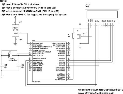
You will need a PIC18F4520 chip running at 20MHz attached with a standard 16×2 LCD Module and LM35 on AN0 pin. LM35 is a 3 pin device as show below.
connect the +Vs Pin to 5v and GND to GND. The output must be connected to the analog input pin 0 of the PIC18F4520 MCU. It is labeled AN0 in the datasheet. It is pin number 2 on the 40 pin package. It is also called RA0 because it is shared with PORTA0.
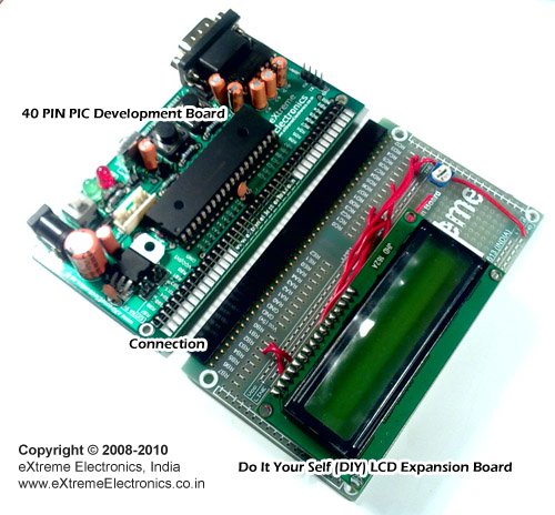
We will use our 40 PIN PIC Development board to realize the project. The base board has all the basic circuit to run the PIC. The extra part required for this project like LCD and the LM35 temperature sensor are installed in the expansion board.
The supply for LM35 can be taken from the onboard extra power supply. See the image below.
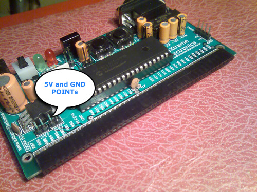
Just use single PIN female to female wire to connect with the leads of LM35 temperature sensor. Now plug the LCD Expansion board into the expansion slot and burn the hex file to the board using a PIC ISCP Programmer. Your are now all ready to run.
C Source Code For PIC Thermometer Project.
/********************************************************************

LM35 Temperature Sensor INTERFACING TEST PROGRAM

---------------------------------------------------------
Simple Program to connect with LM temperature sensor using the
internal ADC of PIC MCU.

The program displays the current environment temperature on
LCD Module.

MCU: PIC18FXXXX Series from Microchip.
Compiler: HI-TECH C Compiler for PIC18 MCUs (http://www.htsoft.com/)

Copyrights 2008-2010 Avinash Gupta
eXtreme Electronics, India

For More Info visit
http://www.eXtremeElectronics.co.in

Mail: [email protected]

********************************************************************/
#include <htc.h>

#include <math.h>

#include "lcd.h"

//Chip Settings
__CONFIG(1,0x0200);
__CONFIG(2,0X1E1F);
__CONFIG(3,0X8100);
__CONFIG(4,0X00C1);
__CONFIG(5,0XC00F);


//Simple Delay Routine
void Wait(unsigned int delay)
{
   for(;delay;delay--)
      __delay_us(100);
}

//Function to Initialise the ADC Module
void ADCInit()
{
   //We use default value for +/- Vref

   //VCFG0=0,VCFG1=0
   //That means +Vref = Vdd (5v) and -Vref=GEN

   //Port Configuration
   //We also use default value here too
   //All ANx channels are Analog

   /*
      ADCON2

      *ADC Result Right Justified.
      *Acquisition Time = 2TAD
      *Conversion Clock = 32 Tosc
   */

   ADCON2=0b10001010;
}

//Function to Read given ADC channel (0-13)
unsigned int ADCRead(unsigned char ch)
{
   if(ch>13) return 0;  //Invalid Channel

   ADCON0=0x00;

   ADCON0=(ch<<2);   //Select ADC Channel

   ADON=1;  //switch on the adc module

   GODONE=1;//Start conversion

   while(GODONE); //wait for the conversion to finish

   ADON=0;  //switch off adc

   return ADRES;
}
void main()
{
   //Let the LCD Module start up
   Wait(100);

   //Initialize the LCD Module
   LCDInit(LS_BLINK);

   //Initialize the ADC Module

   ADCInit();

   //Clear the Module
   LCDClear();

   //Write a string at current cursor pos
   LCDWriteString("LM35 Test");
   LCDWriteStringXY(4,1,"Degree Celcius");

   while(1)
   {
      unsigned int val; //ADC Value

      unsigned int t;      //Temperature


      val=ADCRead(0);   //Read Channel 0

      t=round(val*0.48876);//Convert to Degree Celcius

      LCDWriteIntXY(0,1,t,3);//Prit IT!


      Wait(1000);
   }

}
To compile the above code, lcd.c file must be added to the poject. While the lcd.h, myutils.h must be present in the same project folder. More instruction is available in following articles.
Testing The LM35 Based Thermometer.
Turn on the power supply, the screen should show the current temperature readings. Bring a Hot soldering iron tip near the LM35’s pins, don’t touch it keep it 1 or 2mm away. The screen should update with the rising temperature. Now finally touch the pins of LM35 with the tip of iron, the temperature should rise quickly. Keep it there until temperature rise to 80 degrees, then remove the iron. You can now blow some air by your mouth on the sensor to cool it down.
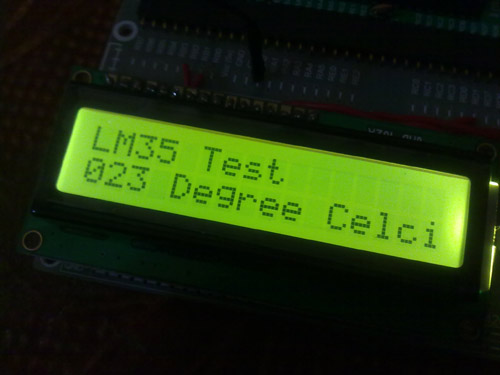
Fig.: LM35 Temperature Sensor Demo.
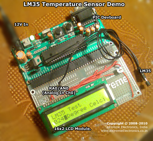
Fig.: LM35 Temperature Sensor Demo Hardware Setup.

PIC18F4520 based Thermometer using LM35 Schematic
General Notes
- For proper working use the components of exact values as shown above.
- Wherever possible use new components.
- Solder everything in a clean way. Major problems arises due to improper soldering,solder jumps and loose joints.
- Use the exact value crystal shown in schematic.
- Only burning the HEX file to the MCU is NOT enough. PIC18 devices are fairly complex MCU and can be configured in various ways. Chip is configured using the CONFIG Bytes. Although all hex file given in our site comes with embedded CONFIG bytes. But the user must ensure they are programmed to the chip. Any good programmer has the capability to read the configuration information from the hex file and transfer it to the MCU. Programs will not run without proper configuration byte programming. One major job of configuration is to setup proper oscillator and PLL modes without which the MCU won’t execute a single instruction.
- To compile the above code you need the HI-TECH C and MPLAB IDE. They must be properly set up and a project with correct settings must be created in order to compile the code. So I request you to read the following articles to become familiar with the built steps.
- To understand the code you must have good knowledge of core C language. Please don’t be confused with the basic concept of the language.
- You must be familier with project concept and multi source file concept that used used in most professional languages like C.
- You need Proteus VSM if you want to develop or debug the project without any hardware setup.
Video
Source : Interfacing LM35 Temperature Sensor with PIC Microcontroller.
- How is the LM35 powered and connected to the PIC?
The LM35 +Vs pin is connected to 5V, GND to ground, and the output is connected to the PIC analog input AN0 (RA0, pin 2). - How do you convert ADC readings to temperature?
Use t = round(val * 0.48876) where val is the ADC reading (0-1023) to get temperature in degrees Celsius. - Which ADC channel is used for the LM35?
ADC channel 0 (AN0) is used for the LM35 output. - What compiler and files are required to build the project?
HI-TECH C compiler for PIC18 and MPLAB IDE are required, and lcd.c, lcd.h, and myutils.h must be in the project folder. - What must be ensured besides burning the HEX file to the MCU?
Ensure configuration bytes (CONFIG) from the hex are programmed correctly, including oscillator and PLL setup; otherwise the MCU may not run. - How can you test the LM35 thermometer hardware?
Power the board, observe the LCD temperature, bring a hot soldering iron near the LM35 to see rising readings, then cool the sensor by blowing on it. - What ADC settings are used in ADCInit in the code?
ADCON2=0b10001010: right-justified result, acquisition time = 2 TAD, conversion clock = 32 Tosc; +Vref = Vdd and -Vref = Vss by default. - Do you need any simulation tools for development?
Proteus VSM is suggested if you want to develop or debug without hardware.