Summary of Infrared Camera on the PIC32
This project integrates a FLIR Lepton thermal camera with a PIC32 microcontroller to display heat maps on a TFT screen. The system utilizes SPI for data transfer and I2C for camera configuration, while servos enable pan-tilt functionality. It supports three image modes (Raw14, AGC, RGB888) and two display modes (1-Screen, 4-Screen), the latter stitching multiple frames for a wider field of view.
Parts used in the Thermal Imaging Project:
- PIC32 Microcontroller
- FLIR Lepton Camera
- TFT Display Screen
- Pan-Tilt Servo Assembly
- SG92R Mini Micro Servos
- I2C Communication Interface
- SPI Communication Interface
- Pushbuttons (Button A, B, C)
- External Power Supply (3.3V)
- MATLAB Script for Logo Processing
Introduction
The purpose of this project was to create thermal images displayed on the TFT screen of the PIC32 using data inputted through a thermal camera. A thermal image is an image where the colors are representative of the amount of heat radiated by that location. We used a FLIR Lepton Camera that takes frames of its surrounding via long wave infrared waves.
The camera is actuated through a pan-tilt servo. The PIC32 controls the servos with Pulse-Width-Modulation (PWM) signals. After a frame is transferred from the thermal camera to the PIC32, the servos move to their next position. We are also programming the PIC32 to be able to switch between the 1-Screen (1-Scr) Mode and 4-Screen (4-Scr) Mode. In 1-Scr Mode, the PIC32 displays only 1 frame on the TFT. In 4-Scr Mode, the PIC32 displays 4 frames on the TFT, and the servos rotate between 4 different positions. The 4-Scr Mode stitches together multiple different minimized images to create a larger field of view.
The data from the thermal camera is transferred to the PIC32 through 8-byte transactions via SPI protocol. Every frame consists of 60 packets of data where each packet represents a row of data from the camera. Every packet contains data for each pixel in the row. After a frame is received, the entire frame is processed and printed on the TFT display screen. There are three modes of the camera: Raw14, Automatic Gain Control (AGC), and Red-Green-Blue 888 (RGB888). To change the camera’s data mode, we are using I2C protocol to issue commands to the camera’s control interface.Raw14 is a reading of the thermal intensity on a gray-scale. AGC is a modified version of the Raw14 where the thermal value is compressed from 16 bits to 8 bits. To prevent a loss of gray shades, the number of gray shades devoted to a particular intensity range is dependent on the frequency of the intensity in the data set. RBG888 is a color map of the image. Yellow represents the hottest objects, and black represents the coolest objects.
We successfully created thermal images in all three modes and processed the data in both 1-Scr and 4-Scr modes. We integrated the servos to the system and designed a UI to control the data mode and the processing mode.
High Level Design
Rationale and Sources behind Project Idea
We wanted to do a project that would not only challenge us technically, but also have a practical application. From a technical perspective, this project allowed us to implement multiple communication protocols, image processing algorithms, and incorporate servo movements. One possible application of thermal imaging is medical imaging for blood flow. Thermal imaging is a non-invasive, efficient method of tracking blood flow in the human body. More information on this topic can be found here.
Logical Structure
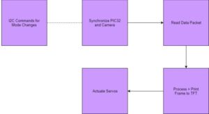
Creating a thermal image in Raw14, AGC or RBG888 mode involved the following steps:
1. Issue Commands to the thermal camera’s Command Control Interface (CCI) that change to AGC or RGB888 modes
2. Synchronizing the PIC32 and the Thermal Camera
3. Transferring one frame of data from the Thermal Camera to the PIC32
4. Processing the frame on the TFT
5. Actuate the servo to the desired location
These steps will be explained further in the Software Design section.
Hardware & Software Tradeoffs
One significant decision that we made was to de-synchronize the camera from the PIC32 after taking a frame. De-synchronizing gives us an extended time frame to process and print the data to the TFT before we obtain another frame of data. De-synchronization after every frame is considerably simpler and easier to integrate at the cost of real-time efficiency as explained below.
The camera continuously streams thermal data while synchronized. The solutions with periodic processing were complex and challenging. If we cause a time delay through yielding to other protothreads or performing other operations in the original protothreads, we lose synchronization between the PIC32 and the camera. Because we needed to process and print the data, putting the data transaction software in a protothread while maintaining synchronization is challenging.
One possible solution is to maintain synchronization by putting the data transaction software in an ISR. The problem is that the processing and printing algorithms take substantially longer than multiple data transactions and requires storage for the input data. The camera streams at 10 Mhz and quickly accumulates more sets of data than the PIC32 can store before even one set of data is processed and printed.
Another possible solution is to discard the new data until the processing and printing are finished for one frame. The problem with this solution is dealing re-gaining synchronization in the event of synchronization loss. We would need to regain synchronization through a time-out, account for an unknown number of discard packets and also keep track of how much of the frame has been transferred to the PIC. This software for re-gaining synchronization would also need to integrate with the ISR’s timing constraints and the timing constraints of the processing and printing algorithms.
Another decision that we are making is to transfer data via single SPI transactions rather than using Direct Memory Access (DMA). The main issue is the variable length of the input data. The variable data length causes to us to not know how much memory to allocate for the data transfer and where the discard packets stop. This makes DMA unusable because the only solution is overestimating memory space allocation when space is limited.
Another design decision that we are making is to have the user-interface for mode transitions be primarily software-based. We designed a pushbutton system that rotated between Raw14, AGC and RBG888 respectively. The camera cannot be in RBG888 mode without having AGC already enabled. Limiting the user to this order prevented the user from ever trying to enable RBG888 without having AGC enabled.
Relationship of our design to available IEEE, ISO, ANSI, DIN, and other standards.
We used the NXP and IEEE standards for I2C [1] and SPI [2] Communication Protocols.
Existing patents, copyrights, and trademarks which are relevant to our project.
Many patents exist for thermal imaging, but we did not examine any of them while we were creating this project.
Software Design
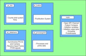
There are 4 protothreads in our system: pt_tick, pt_datatrans, pt_processprint, pt_button. The purpose of each protothread is outlined below in Figure 2.
SPI Data Transactions
We opened up the SPI channel using the function SpiChnOpen with 8-bit transactions in SPI mode 3 (CPOL=1, CPHA=1). We set the SPI Channel to operate at a frequency of 10 MHz by dividing the overall clock frequency (40 MHz) by 4. The thermal camera can operate between 2 MHz and 20MHz [3].
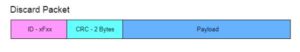
In protothread_datatrans, we begin by synchronizing the PIC32 and the camera. The first step is to stop the camera for at least 200 ms. The next step is to begin taking data through SPI transactions. The camera transmits discard packets until it is ready to begin transmitting data from the frame. In a discard packet, the first four LSB bits of the packet consist of the Hexadecimal F.
We initiate this data transmission with the following steps: setting the 8-bit mode, writing junk data to the camera via the MOSI line, waiting for the transaction to end and then reading the SPI packet via the MISO line. If we detect a discard packet by checking the first byte of the packet, then we do not store the rest of the incoming packet in an array. When the first non-discard packet comes from the camera, we store the packet and break out of the loop. We then transition into a for-loop where we initiate the data transactions for the rest of the frame. The transmitted data is stored in an array that another protothread will process and print. The final step is to let the other protothreads know that one frame has arrived in its entirety.
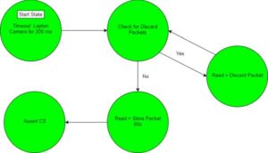
Image Processing Algorithm
Once a frame has been taken, we store the data in a double array named frame_data. frame_data contains a row for each packet in the frame and a column for each byte in the packet. Every entry in frame_data is a one byte chunk of thermal data that represents a specific pixel in the camera’s area of vision.
The TFT contains 240 pixels in the x-direction and 320 pixels in the y-direction, and the camera contains 60 pixels in the x-direction and 80 pixels in the y-direction. This causes a 4-by-4 pixel square on the TFT to represent one pixel on the camera. We created two separate arrays of x and y coordinates, LineCoords and PixCoords, in main. The index of an element in the frame_data array is a pixel coordinate on the camera, and the value of the element is the coordinate of the upper left corner of a 4-by-4 square on the TFT.
We then implemented this mapping by parsing through the frame_data array and printing a colored, 4-by-4 square to the TFT. The coordinates of the square’s upper left corner are corresponding to an element of PixelCoords and LineCoords. See Figure 6 for further explanation.
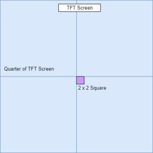
When we switched to 4-Scr mode, we printed 4 separate images onto 4 separate sections of the TFT. Each section consists of a 120-by-160 pixel section on the TFT which is one fourth of the screen. To map the data frame to this truncated pixel area, we printed 2-by-2 squares to the TFT for every pixel from the camera. To print the square, we modified the coordinates used in 1-Scr mode by halfing and offsetting the coordinates. We repeated this process for all four sections on the TFT.
The top left and top right images in 4-Scr mode are processed at an angle. This is due to the angle of the camera when it is tilted and rotated by the servos. The camera perceives vertical images at approximately a 35 degree tilt. The top left image is 35 degrees Counterclockwise (CCW) from vertical and the top right is 35 degrees Clockwise (CW) from vertical. To account for this, we rotated the top left image 26.6 degrees CW and the top right 26.6 degrees CCW. The resolution of the TFT limited the angle rotation of the image.
To rotate by 26.6 degrees, we shift blocks of the image. The following is an example of printing a 26.6 CW rotated image to the top left quarter of the TFT screen beginning with the leftmost column. The first two columns of pixels fill the first two columns and rows 1:120 on the TFT. The next two columns fill columns 3 and 4 and are shifted down one pixel such that they fill rows 2:121. The next two columns fill columns 5 and 6 and fill rows 3:122. This process repeats until column 160 is reached which fills rows 81:200.
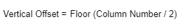
Equation 1: Top Left Vertical Rotational Offset
The equation for the top left vertical rotational offset is above.
To rotate the top right image 26.6 degrees CCW, the same approach is taken except that we begin at column 161 and shift up instead of down.
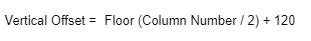
Equation 2: Top Right Vertical Rotational Offset
The equation for the top left vertical rotational offset is above.
Changes in Mode
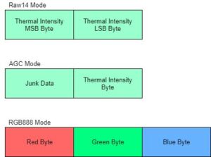
The thermal camera’s default mode is Raw14. The data in Raw14 is a reading of the intensity for each pixel. In Raw14 mode, the camera transmits two bytes of thermal data for every pixel in the camera. This causes the payload to be 160 bytes because there are 80 pixels. Given the MSB byte for the pixel, we shift the byte left. We receive the LSB byte next and concatenate it with the MSB byte. The concatenated value is the color that we will print on the TFT.
Thermal data in AGC is only one byte per pixel. Even though only 80 bytes are necessary, the payload is 160 bytes. There is no change in communication protocol from Raw14 to AGC. The color is the LSB byte of the data transferred for the a given pixel. The MSB byte is just junk data.
RGB888 is a separate mode where the data for each pixel contains 3 bytes – a Red byte, a Green byte and a Blue byte. The total payload is 240 bytes. The color input to the TFT function is only 16 bits. We transformed the RGB888 data to RGB565 by concatenating the 5 LSB bits of the Red data, the 6 LSB bits of the Green data, and the 5 LSB bits of the Blue data.
Transitioning between Modes
The protothread_button is used to detect downward pushes for multiple buttons. A button push will trigger a mode change for the system. Button B toggles the printing mode between 1-Scr and 4-Scr. When Button B is pressed, the 4-Scr flag is toggled in one direction and the 1-Scr flag is toggled in the other direction. In other words, if 4-Scr flag is True, then it will become False. If 1-Scr flag is False, then it will become True. The result is that the flags always opposite to each other.
Button A controls changes to the mode of the outputted thermal data. It causes the system to rotates between the three aforementioned data modes. When Button A is first pressed, the protothread transitions from Raw14. On a second push, the protothread transitions to AGC. On a third push, the protothread transitions to RGB888. Finally, on a third push, the protothread loops back to Raw14. In each instance, the button press triggers an I2C function that communicates with the camera’s CCI.
Button C enables and disables the PWM signals to the servos. This turns the servos on and off, and controls the camera’s field of view. When the third button is pushed, the protothread toggles the flag control PWM signal output.
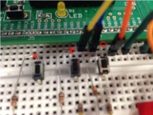
See Figure 10 for pushbutton labeling.
Pulse-Width-Modulation (PWM)
The pan-tilt servo sub-system uses two SG92R Mini Micro Servos to pan left and right and tilt up and down. The servos require a new PWM signal every 20 ms [4]. In other words, the signals are issued at a frequency of 50 Hz. The pulse length can range from 1 ms to 2 ms.
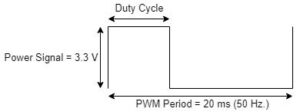
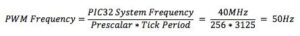
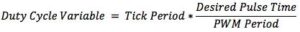
A pulse of 1ms corresponds to a -90° servo rotation. A pulse of 1.5ms corresponds to a 0° servo rotation and a pulse of 2 ms corresponds to a 90° servo rotation. To generate this signal, two output compare modules (OC) were used with two timers. To set the PWM Output Signal Frequency to 50 Hz, Timer 2 and Timer 3 were both set with a pre-scalar of 256 and time period of 3125 ticks from the system. This results in the following equation:
To set an angle on a servo, the pulse time is set between 1ms to 2ms. The following equation determines what number to assign to the duty cycle variable:
OC3 controls the Tilt servo. OC4 controls the Pan servo. Both are configured as a PWM source. The servos rotated between 4 different pan-tilt servo coordinates that form a rough square. Once the servos finish rotating, the PIC32 processes one frame of data. In 4-Scr mode, 1 servo location out of the 4 represents one fourth of the TFT screen.
I2C Data Transactions
We are using I2C protocol to communicate with the CCI on the Lepton board. The I2C.h header file contains the functions which setup and transmit the data to and from the camera. The LeptonCommand function takes in the following inputs: a read or write bit, command, moduleID, and commandID. The read or write bit tells the camera whether to receive or send data. The command variable sets whether or not the camera sets, gets or runs something. The camera has multiple modules. In this program, we use the OEM and AGC modules for the moduleID. The AGC module controls the Automatic Gain Control settings. These settings affect image brightness and contrast. The OEM module contains commands for FLIR’s OEM customers. The commandID identifies which command the camera uses.
The following procedure is followed to communicate with the CCI:
1. Poll the status register until camera is ready for a new command.
2. If executing a command rather than solely reading, send the command to the camera using the camera’s received data registers.
3. Write the number of data words written to the received data length register.
4. Writing the desired command ID to the Command Register.
5. Polling the Status Register to determine when the command is completed.
Whenever a command is executed, the camera raises the busy bit for the duration of the command. When the busy bit is clear, we know that the CCI is ready for a new operation. The status register for this busy bit is 0x02.
The Camera’s data register address is 0x08. In our application, we only write 2 bytes of data to the camera. Thus, we write 0x02 to the data length register which is located at 0x06.
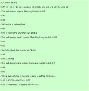
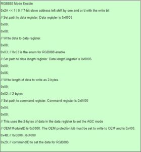
One other piece of information to note is that AGC is enabled before RGB888 because RGB888 cannot function without having AGC enabled.
Here is the ordered stream of data that was written to the CCI to enable AGC mode and then to enable RGB888 mode.
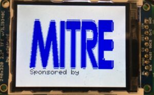
Mitre Logo
We wanted to show our appreciation for the Mitre Corporation for funding us, so we display a MITRE logo upon startup. The MITRE logo we chose was too large to put on the PIC32 because it is limited to 32kB of flash memory. We create a MATLAB script that parses an image of the MITRE logo. The MITRE logo is only white and blue. The script records where the color transitions occur in an array. This relatively small array of transitions is loaded onto the PIC32 as a header file. It is then translated by the code in main.c into colors at locations on the TFT LCD Display.
Hardware Design
I2C Hardware Protocol
The I2C lines SDA and SCL on PIC32 were connected to the SDA and SCL pins on the Lepton break-out board. On the PIC32, SDA was connected to pin RB9 and SCL to pin RB8. The PIC32 does not have internal pullup resistors for I2C, so two external 2.4kΩ resistors were used to pull-up SDA and SCL to 3.3V on the big board. The schematic in Appendix C: Figure 25 details this layout.
SPI Hardware Protocol
The SPI protocol is master-slave configuration. The PIC32 acts as the master, and the camera acts as the slave. There are 4 lines in this configuration: CS, CLK, MISO and MOSI. The MOSI line is grounded in this set-up because the camera cannot take data via the MOSI line. The MISO line from the camera is connected to the PIC32’s SPI data input channel. Thermal data is transferred using this line. The CLK signal from the PIC32 lets the PIC32 and the camera have the same clock frequency. The CS line lets the PIC32 tell the camera when to send data to the PIC32. The schematic in Appendix C: Figure 26 details this layout.
Servos
There are two servos used to control the pan rotation and tilt of the pan-tilt servo assembly. The pan and tilt servos are connected to pins RPB13 and RPB10 respectively. The servos consume up to 500mA when rotating, so they are connected to an external power supply. The voltage for this power supply is set to 3.3V. The power supply and servos shared a common ground with the PIC32. The schematic in Appendix C: Figure 27 details this layout.
Each pushbutton has a connection on the source side to a 330 Ohm resistor that is connected to 3.3V. The drain side has a 10 kOhm in parallel connected to ground which brings the source side to 0v when the button is not pressed. The drain side also has a wire in series connected to an input pin on the PIC32. Pushbutton A is connected to pin RA0, pushbutton B is connected to RB3, and pushbutton C is connected to RA4. These three pins are configured as inputs and have high impedance. The schematic in Appendix C: Figure 28 details this layout.
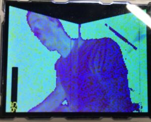
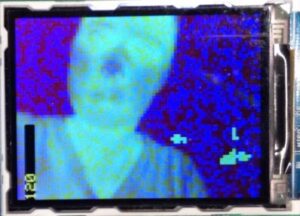
Results
The resulting images from our system are below. The specifications of the images are discussed in other sections.
Conclusions
Results vs. Expectations
We were pleased with the results of this project. Our system constructed images on the TFT that were sensitive to a few degrees in temperature. The sensitivity in degrees was demonstrated by a user who rubbed their hands together to create a small heat change on their hands. The change in heat was noted by the image on the TFT. See Figures 23 and 24 for further explanation.
The system also created images that accounted for more dramatic heat differences. We placed a cup of hot water and cup of cold water in front of the camera, and the image on the TFT showed a substantial color change between the two cups. See Figure 22 for further explanation. We also placed a soldering iron in front of the camera, and an even more dramatic color change appeared on the TFT screen. See Figures 16-20 for further explanation.
One element of the project that we could have improved was to do a thorough timing analysis of the entire system. We have multiple yield statements scattered throughout the software. A yield statement causes a protothread to allow other protothreads to take over the PIC32 for a specified number of seconds rather than the original protothread continuing to run without interruption. Some yield statements have a specific purpose, while others are general estimate of the time needed. The rate of imaging could potentially be increased by reducing the amount of time that the a protothread yields to another protothread. This idea is especially prevalent for the yield statements where the specified amount of yield time is an estimate.
While synchronization is maintained, the Lepton Camera sends a unique frame three times before it sends an new frame. In our system, we only receive one frame of data. We could have received two or three frames of the same set of data and averaged the values at each pixel.
Further work can be done to enhance the stitching algorithm. The stitching between the top and bottom images are continuous, but the stitching between the top left and top right needs work. Images are duplicated near this intersection and the rotation is not fully corrected. Furthermore, the rotation equations distort the images.
Applicable Standards
Our implementation of SPI communication protocol was in adherence to the IEEE standard. The FLIR Lepton Camera registers are 16-bits wide instead of 8-bits, so only 16-bit data transfers are allowed. This is a break from the NXP standard. Other than this difference, our implementation adheres to the NXP Standard.
Intellectual Property Considerations
We modeled our design after standard examples given throughout the class. We modeled our I2C code after the example code from the FLIR Lepton Github Open Source code [5].
We used a protothreads library created by Adam Dunkels, and a TFT library created by AdaFruit and Syed Tahmid Mahbub. We used Microchip-generated peripheral software libraries that were constructed for the PIC32 [6]. All three libraries were released into the public domain.
We are not reverse-engineering a design. Thermal imagers are commercially available, so there are no patent opportunities. There is a publishing opportunity for this project because the detailed use and integration of a Microcontroller, Servo System and a Thermal Camera is an educational opportunity.
Ethical Considerations
This project highlighted our desire to fulfill IEEE standard 5. Standard 5 states that we must, “to improve the understanding by individuals and society of the capabilities and societal implications of conventional and emerging technologies, including intelligent systems.” Thermal images are easy for the average person to understand because the vast majority of people understand heat. A thermal imaging system can also be applied to common problems like night vision and heat loss analysis in homes.
This project also incorporated our adherence to IEEE standard 6. Standard 6 admonishes us, “to maintain and improve our technical competence and to undertake technological tasks for others only if qualified by training or experience, or after full disclosure of pertinent limitations”. We choose a project that was within our technical grasp and allowed both of us to make a substantial technical contribution.
Furthermore, our imaging system did not discriminate against or injure anyone in accordance with Standards 8 and 9 respectively. Standard 8 states that we must “treat fairly all persons and to not engage in acts of discrimination based on race, religion, gender, disability, age, national origin, sexual orientation, gender identity, or gender expression.” Standard 9 states that we must “avoid injuring others, their property, reputation, or employment by false or malicious action.”
Source: Infrared Camera on the PIC32
- How is thermal data transferred from the camera to the microcontroller?
Data is transferred via 8-byte transactions using the SPI protocol. - Can the system switch between different display modes?
Yes, the system toggles between 1-Screen Mode and 4-Screen Mode using Button B. - What components control the camera's viewing angle?
Two SG92R Mini Micro Servos actuate the pan and tilt movements. - Does the camera support multiple color mapping modes?
The camera supports Raw14, Automatic Gain Control (AGC), and Red-Green-Blue 888 (RGB888) modes. - How does the 4-Screen Mode create a larger field of view?
It stitches together four minimized images captured at different servo positions. - Why was Direct Memory Access not used for data transfer?
The variable length of input data made DMA unusable due to memory allocation constraints. - What is the required frequency for the PWM signals sent to the servos?
The servos require a new PWM signal every 20 ms, which corresponds to a frequency of 50 Hz. - How are pushbuttons utilized to change the system state?
Button A cycles data modes, Button B switches display modes, and Button C enables or disables the servos.