Summary of How to generate video signals in real-time using a PIC16F84
This article explains how to generate real-time video signals using a PIC16C84/PIC16F84 microcontroller, detailing PAL TV standards, scan-line timing, and synchronization pulses. The author shares their experience creating Pong and Tetris games in software, emphasizing the need for precise voltage levels (0–1V) and hardware components like resistors for digital-to-analog conversion to drive a standard TV set.
Parts used in the Video Signal Generation Project:
- PIC16C84 microcontroller
- PIC16F84 microcontroller
- Vacuum tube television with phosphor screen
- Electron cannon
- Magnets for beam deflection
- Resistors for 2-bit digital-to-analog conversion
Background
During the Christmas holidays 1997-1998, I started on a small project, trying to generate a video signal with a PIC16C84. I had seen some video clock generating video signals in software, and thought it was a quite interesting idea, and wanted to take it a step further. I didn’t know much about video signals back then, I basically just had seen how a single scan-line works. But during the spring I learned more and succeeded in making the game Pong with a PIC16C84. I thought this was quite cool, so I made it available on the Internet, and during the summer I also made the game Tetris. I had a lot of feedback about them, from people telling me how cool it is, and from people who actually built the games. From this feedback I guess that probably 100-200 people have built my games, which is much more than I expected. A lot of people ask me stuff about video signals and how these games can generate a video signal in real-time in software, so that’s why I’m writing this small piece of text about how to generate video signals in real-time. Hopefully this text will help you to understand video signals and how my games work.
To understand anything about generating video signals in real-time, one must know how video-signals work in detail, so before we look at any code we’ll have to talk about video signals.
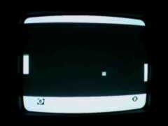 How a standard TV-set works.
A standard TV-set is built with a vacuum tube, which has a phosphor screen that an electron canon shoots at. When the electrons from the cannon hits the screen, light is emitted from the phosphor as long as the canon shoots electrons at it, and it also has a short afterglow. The electron beam from the electron-cannon can be bent using magnets so it shoots at different parts of the screen. If this is controlled so it draws horizontal lines all over the screen repeatedly, while the intensity of the beam is controlled, an image can be drawn on the screen. The screen is redrawn 25 times per second on a PAL system, but to reduce flickering the image is interlaced, showing first all odd lines then all even lines, so the image is partially updated 50 times per second. To get color each dot on the screen is divided into three colors: red, green and blue, however here we’ll only discuss black and white television, because that is only what is possible to generate real-time in software. (With a PIC16F84 anyway)
Different TV standards
There are three major TV-standards: NTSC, SECAM and PAL. The NTSC (Short for “National Television System Committe”, but back in the early days of TV there was problems with getting the same color over the whole picture so a more evil interpretation of the letters is that it stands for “Never The Same Color” ) is the American TV-standard, it has only 525 scan-lines, but it has a update frequency of 30Hz. SECAM (Short for “SEquential Color And Memory”, but as the French usually want to get their own solution to problems, a more evil interpretation is that it stands for “System Essentially Contrary to the American Method”) is the French TV-standard, it has improved color stability and higher intensity resolution but with less color resolution, I don’t know much about that standard. The European standard is PAL (Phase Alternating Lines, or as a PAL enthusiast would interpret the letters: “Perfect At Last”), it has 625 lines per frame, 25 frames per second. It is based on NTSC, but the color-coding has been improved by using a phase shift on every other line to remove the color errors that occurred with NTSC. In this document I will focus on the PAL.
The information in the video signal
The image seen on the screen has different intensities. As the electron beam sweeps over the screen, the intensity that should be at the position of the beam, is sent as a voltage level in the video signal.. There is no information in this intensity information about where the electron beam is on the screen. To solve this, a synchronization pulse is sent in the beginning of each line to tell the TV that the current line is finished and move down the electron beam to the next line. (Like the <Enter> key on the keyboard, when writing a text with a computer) The TV must also know when a new image is coming, this is done by making a special synchronization pattern. (Like the “new document” function when writing a text with a computer) An image that is updated 25 times per second would be quite flickering, so therefor all even lines are drawn first and then all odd, this method shows 50 half images per second, making the picture have less flickering. The information whether the image contains even or odd lines are sent in the vertical synchronization pattern, as different patterns for odd and even images. The video signal has a voltage range 0 to 1V, where 0.3V represents black, and 1.0V is white (gray intensities have voltages between these values). Levels close to zero represent synchronization pulses
The scan-line
The image is divided into scan-lines, it is the most important part of the image since it contains the image data. The scan-lines are all 64us long. First a 4us long sync pulse is sent, by setting the signal level to 0V, to tell the TV that a new line is coming. The old TV’s was kind of slow, so they needed 8us after the sync-pulse to get the electron beam in position. During this time the signal is kept at black level. The 8us delay is followed by the image data for 52us, drawn on the screen from the left to the right with the intensities obtained from the video signal. Black is represented by 0.3V and as the voltage increases the intensity increases, with the maximum intensity at 1.0v (white). See the image below to see the scan-line.
Putting the scan-lines together to an image
An image is built from 625scanlines, but a TV doesn’t show 625 lines. Some of the lines are used for synchronization pulses, and some lines are invisible (I don’t know exactly how many) because old TVs needed some time to move the electron beam from the bottom of the screen. (Those invisible lines are nowadays used for other purposes, Text-TV for example).
The vertical synchronization pulses.
To tell the TV that a new image is coming, a special pattern of synchronization pulses is sent. Since the picture is built from two half pictures, the pattern is different for the odd and even images. The vertical synchronization pulses looks like this
Ok, this is the part about how to create the video signal in software, it will not be possible to understand if you don’t understand the video signal stuff described above.
When you know how a video signal should look like, it is quite easy to generate it in software if you have unlimited processing power. The problem is that it requires a lot of power from the processor, but if you don’t have a powerful processor it can be done anyway, by thinking before writing the code.
In my code examples in this part I will use the two following macros:
DNOP – dual nop, a macro to wait for two clock cycles, instead of two nops
DELAY – a delay macro that delays 3 times the number of clocks in the W-register.
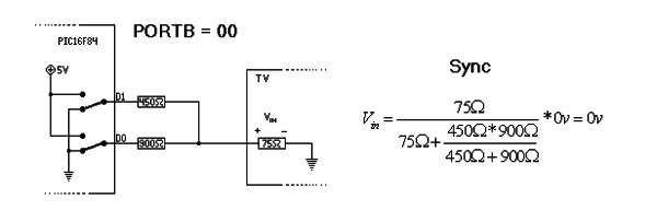
The hardware
To be able to generate a video signal, some hardware is needed to be able to generate signal levels between 0 and 1V. To get a picture you’ll need at least 3 levels. The TV needs sync and black level to be able to lock on the video signal. If you want more than a black image you’ll need some gray or white level. Some kind of digital to analog converter is needed, with at least 2bits to get enough levels. The input impedance of the composite input on a standard TV is 75 Ohms, and by using two resistors a 2-bit DA can be created (as in the images below) thanks to voltage division.
For more detail: How to generate video signals in real-time using a PIC16F84
- How does a standard TV-set draw an image?
An electron cannon shoots electrons at a phosphor screen, which emits light when hit; magnets bend the beam to draw horizontal lines repeatedly while controlling intensity. - What is the update frequency of a PAL system?
A PAL system redraws the screen 25 times per second, but interlacing updates the image partially 50 times per second to reduce flickering. - Which voltage level represents black in the video signal?
The voltage level of 0.3V represents black, while 1.0V represents white within the 0 to 1V range. - How long is a single scan-line in the PAL standard?
Each scan-line is 64 microseconds long, consisting of a 4us sync pulse, an 8us delay, and 52us of image data. - Why are some scan-lines invisible on a TV screen?
Some lines are invisible because old TVs needed time to move the electron beam from the bottom of the screen back to the top. - What hardware is required to generate signal levels between 0 and 1V?
A digital-to-analog converter is needed, which can be created using two resistors for voltage division to achieve at least 2 bits of resolution. - Does the document focus on NTSC or PAL standards?
The document focuses on the PAL standard, which has 625 lines per frame and uses phase shifting to improve color stability. - What macros are used in the code examples for timing delays?
The code uses DNOP for waiting two clock cycles and DELAY to delay three times the number of clocks stored in the W-register.