


Summary of Voltage monitor for car’s battery and its charging system PIC16F1827
This article describes a DIY electronic voltage monitor for a 2010 Equinox battery and charging system. The device plugs into the cigarette lighter, using a PIC16F1827 microcontroller to measure instantaneous voltage via an internal Fixed Reference Voltage (FVR) module. It displays readings on a 4-digit seven-segment LED, providing early warnings for faulty charging systems by detecting if voltage deviates from the standard 13.8V range when the engine is running.Parts used in the Car Battery Voltage Monitor:
- PIC16F1827 Microcontroller
- LM7805 Regulator IC
- 4-digit seven segment LED display
- R1 Resistor
- R2 Resistor
- 5.1 V Zener diode
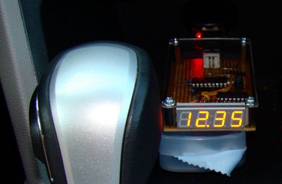
My 2010 Equinox has got every feature that a modern automobile should have. However, one thing that I personally find missing is the real-time monitoring of voltage across the car’s battery terminals. This may not seem to be that important but one of the most common reasons for a car battery failure is the faulty charging system. If the charging system is not working properly, the battery will not get the proper charging voltage (about 13.8 V for 12V battery) across its terminals and it could go flat. This project is about making a simple electronic voltage monitor system for car’s battery and its charging system. It plugs into the car’s cigarette lighter receptacle and displays the instantaneous output voltage across the battery terminals on a 4-digit seven segment LED display. This helps you to get early warnings for possible battery and its charging system problems. Microchip’s PIC16F1827 is the main controller in this project, which uses the built-in Fixed Reference Voltage (FVR) module to achieve a very precise and accurate A/D conversion of the battery voltage.
Theory
As I said this project is simply about making a precise digital voltmeter that plugs in to the car’s cigarette lighter receptacle and displays the instantaneous voltage across the battery terminals. When the engine is turned off, the voltage measured by this device is the actual output voltage from the battery. However, if the engine is on or the car is running, it actually measures the charging voltage across the battery that is coming from the car’s charging system (alternator + rectifier). The functional block diagram of this project is shown below.
The +5V power supply for the PIC16F1827 microcontroller circuit is derived from the car’s battery output voltage (usually +12V) using a regulator IC (such as LM7805). The battery terminal voltage is measured through an ADC channel of PIC16F1827. The FVR module inside PIC16F1827 is chosen to derive a stable positive reference voltage of 4.096 V for precise A/D conversion. Before feeding to the ADC channel, the battery output voltage is scaled down to below the reference voltage by using a voltage divider network. The measured instantaneous battery voltage is shown on a 4-digit seven segment LED display.
Read my previous article, Using Fixed Voltage Reference (FVR) for A/D conversion in enhanced mid-range PIC microcontroller, to find more information on the FVR module of PIC16F1827.
Circuit diagram
The circuit diagram of this project is shown below. The PIC16F1827 microcontroller uses the AN4 ADC channel for measuring the voltage across the car’s battery terminals. The R1 and R2 resistors at the ADC input channel creates a simple voltage divider network to scale down the incoming voltage from the battery’s positive terminal. The maximum measurable input voltage at AN4 is 4.096 V (limited by using the internal 4.096 V reference voltage for A/D conversion). Therefore, the maximum input voltage (VBattery) that could be measured without A/D saturation can be obtained from the following equation,
4.096 V = R2*VBattery/(R1 + R2)
Or, VBattery = 16.93 V.
The range of input voltage can be increased simply by lowering the value of R2. The 5.1 V Zener diode is placed in parallel with R2 to prevent the voltage at the microcontroller’s ADC channel from going above 5.1 V. Otherwise, any accidental high input voltage could damage the microcontroller port permanently.
For more detail: Voltage monitor for car’s battery and its charging system PIC16F1827
Quick Solutions to Questions related to Car Battery Voltage Monitor:
- What is the primary purpose of this project?
To create a simple electronic voltage monitor that provides early warnings for possible battery and charging system problems. - How does the device obtain power?
The +5V power supply for the circuit is derived from the car's battery output voltage using a regulator IC like LM7805. - Which microcontroller is used as the main controller?
Microchip's PIC16F1827 is the main controller used in this project. - What reference voltage is used for A/D conversion?
The built-in Fixed Reference Voltage (FVR) module derives a stable positive reference voltage of 4.096 V. - How is the high battery voltage handled before entering the ADC?
A voltage divider network created by R1 and R2 scales down the incoming voltage to below the reference voltage. - Why is a 5.1 V Zener diode included in the circuit?
It prevents the voltage at the microcontroller's ADC channel from exceeding 5.1 V to avoid permanent damage. - What is the maximum measurable input voltage without saturation?
The maximum measurable input voltage is 16.93 V based on the specific resistor values and reference voltage. - Where does the user see the voltage reading?
The measured instantaneous battery voltage is shown on a 4-digit seven segment LED display.
Related projects
Breadboard module for 18-pin PIC16F microcontrollers (PCB version)
Because of their compact size, ease of use and many built-in peripherals, the 18-pin PIC16F series processors (PIC16F628A, PIC16F88, and now PIC16F1827/47)...
Development Boards & Kits · PIC16F1827Breakout board for 18-pin PIC16F series microcontrollers
The 18-pin microcontrollers from PIC16F series have always been my favorite processors. They are small in size (so occupies less area on...
Development Boards & Kits · PIC16F1827Experimenter’s board for enhanced mid-range PIC microcontrollers (PIC16F1827 and PIC16F1847)
The PIC16F628A has always been my first choice for microcontroller-based projects. It is simple, inexpensive, and easily available. Due to its compact...
Meters & Test Instruments · PIC16F688Determine capacitance by measuring the charging time using PIC16F688
When TEST botton is pressed, RA3 pin is set to "1". R2 and R3 are divide the voltage to 1/2 Vra3 which...
Meters & Test InstrumentsFrequency Meter Using Microcontroller
This tutorial simply states how to calculate frequency of a pulse source using a microcontroller. Story https://youtu.be/NAoj-HLRIro This tutorial simply states how...
Meters & Test Instruments · PIC16F84ADigital thermometer with PIC16F84 circuit
This electronic project is a very simple thermometer that is based on the PIC16F84A microcontroller, designed by Microchip. Why to use a...

Ibrar Ayyub
I am an experienced technical writer holding a Master's degree in computer science from BZU Multan, Pakistan University. With a background spanning various industries, particularly in home automation and engineering, I have honed my skills in crafting clear and concise content. Proficient in leveraging infographics and diagrams, I strive to simplify complex concepts for readers. My strength lies in thorough...