The microcontroller used is 0822 zilog encore! 8k series (soic,28pin) as shown on the figure. Is a programmable microcontroller, the functions used are the GPIO and the UART of the chip. GPIO is used on led indicators, and the UART is used for giving and reading AT COMMANDS to control the Bluetooth device.
The whole process of the circuit, is to control the remote device using the 1st board (controller board), to switch a certain load on/off vice versa. Figure 1 explains how to use the controller and figure 2 explains how it functions according to the user. The user will enable the switches for the loads, then the mcu will give commands to the Bluetooth serial, then the remote device will receive the data, to enable the load.
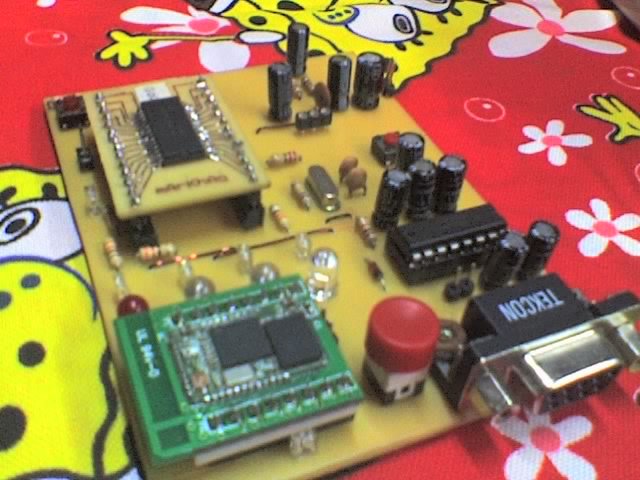
Controller board
The controller board consists of the Bluetooth device, 0822 zilog encore, the max232 IC for programming, DB9 connector and some components, this board has a built in programmer, so it can be re-programmed any time the user wants to.
D9 and D10 is used to indicate connectivity from the other Bluetooth module(the remote device), it should be in the on condition. If it is not, the reset button can be pressed to make a new connection to the remote device. The max232 IC from maxim, is connected to a switch(DPDT, to make it much more cheaper), for either programming or serial communications in the hyperterminal of the PC. D1-D4 is used to indicate the switch status. D5-D9 is optional, it can be used to indicate the status of the load in the remote device, so the programming will be that easy. The power supply of the controller board consists of 3.1265 volts(LM317) and the LM7805 ic. Vout of the LM317 IC can be achieved by the formula:
Remote device board
The main function of the remote device is to accept commands from the BTSerial1, or the controller board, via Bluetooth communications. This will turn ON/OFF the loads that is connected to the relays.
Schematic of the remote device board
The whole schematic is included in the rar file, so it will be easy for the others to see the whole schematics.
For more detail: MCU controlled Bluetooth automation with infrared sensor