Character lcd can perform both read and write functions. Normally lcds are only used to write text on them. Read operation is performed in few nominal tasks. Below are some steps to display text on lcd. I am going to display Character ‘A’ on lcd.
Displaying Text on 16×2 lcd using microcontroller step by step
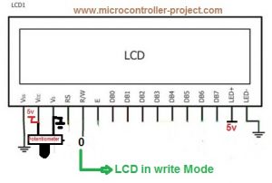
- First select the operation which you want to perform ‘Read’ or ‘Write’. Making R/W Pin of Lcd 0(R/W=0) will select the write operation. Now lcd is set in write mode and you can write any text to lcd. If R/W=1 lcd is set in Read mode and you can read data from lcd. Since i want to display ‘A‘ on lcd. I made R/W=0.
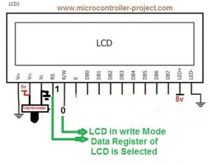
2. Their are two registers in lcd data and command. To display text on lcd you have to select data register of lcd. To execute command you have to select command register of lcd. To select data register make RS=1. To switch to command register make Rs=0. In our case we are displaying text on lcd so make RS=1.
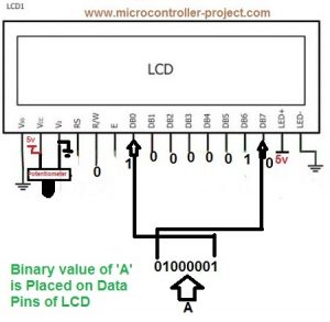
3. Place your text on data pins of Lcd. Since lcd’s data pins are 8-bit wide so place data that is 8-bit wide. Since we want to display ‘A‘ on lcd. ASCII value of ‘A‘ is 65(decimal), 01000001(Binary), 0x41 (Hexadecimal). Place this value on lcd data pins.
4. Now make en=1 and after some microseconds again make en=0. This en signal gives a push to data placed in data register or on data pins to display on 16×2 screen.
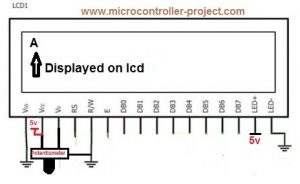
Note: To execute commands steps are same like to display text only difference is in the RS pin selection. To execute commands you have to select the command register of lcd. Make RS=0 to select command register of lcd. Now your commands goes to command register and you can execute them by make en=1 and back to en=0.
Simple text display on 16×2 lcd demo project using 8051 microcontroller
- 16×2 character lcd.
- 89c51 or 89c52 microcontroller.
- Bread board large enough to make circuit on it
- 5 volts DC power supply.
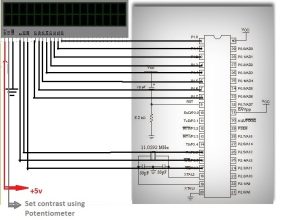
- Potentiometer for setting lcd contrast.
- Software for codding, keil etc
- Burner to burn code in the microcontroller
Dispay text on 16×2 lcd – Project code
Rest of the connections are same as we made in all of our circuits apply 5 volts to vcc pin#40 and Pin#31 of 8051(89c51,89c52). Ground pin#20. Attach crystal of 11.0592MHz frequency in parallel to two 33pf capacitors to pin#18(XTAL1) and Pin#19(XTAL2) of microcontroller. You can also use crystal of any other frequency if you want and capacitors with them can very from 27pf to 33pf.
| #include<reg51.h> | |
| sbit rs=P3^5; //Register select (RS) | |
| sbit rw=P3^7; //Read write (RW) pin | |
| sbit en=P3^6; //Enable (EN) pin | |
| void delay(unsigned int time) //Time delay function | |
| { | |
| unsigned int i,j; | |
| for(i=0;i< time;i++) | |
| for(j=0;j<5;j++); | |
| } | |
| //Function for sending Commands to the command register of LCD | |
| void lcdcmd(unsigned char value) | |
| { | |
| P1=value; | |
| //P3=0x40; | |
| rw=0; | |
| rs=0; | |
| en=1; | |
| delay(50); | |
| en=0; | |
| delay(50); | |
| return; | |
| } | |
| //Function for sending data to the data register of LCD | |
| void display(unsigned char value) | |
| { | |
| P1=value; | |
| //P3=0x60; | |
| rw=0; | |
| rs=1; | |
| en=1; | |
| delay(500); | |
| en=0; | |
| delay(50); | |
| return; | |
| } | |
| //Function to initialize the registers and pins of LCD | |
| //always use with every lcd of hitachi | |
| void lcdint(void) //Function sending commands to lcd. To initialize lcd | |
| { | |
| P1=0x00; | |
| P3=0x00; | |
| delay(15000);display(0x30);delay(4500);display(0x30);delay(300); | |
| display(0x30);delay(650);lcdcmd(0x38);delay(50);lcdcmd(0x0F); | |
| delay(50);lcdcmd(0x01);delay(50);lcdcmd(0x06);delay(50);lcdcmd(0x80); | |
| delay(50); | |
| } | |
| //MAIN FUNCTION | |
| void main() | |
| { | |
| int i,j,k=0,l=0,s=0; | |
| char u[]={“USMAN ALI BUTT“}; | |
| char sec[]={“JUMPING TO SECOND LINE“}; | |
| lcdint(); //Initialize Lcd | |
| lcdcmd(0x01); //Clear Lcd Command | |
| lcdcmd(0x80); | |
| while(u[k]!=‘\0‘) | |
| { | |
| display(u[k]); | |
| k++; | |
| } | |
| delay(100000); | |
| lcdcmd(0x01); //Clear all contents of lcd | |
| lcdcmd(0x80); //Initialize Cursor to first character matrix of lcd | |
| while(sec[s]!=‘\0‘) | |
| { | |
| if(s==15) | |
| lcdcmd(0xC0); //Initializing Cursor to second line first Character matrix | |
| display(sec[s]); | |
| s++; | |
| } | |
| delay(100000); | |
| lcdcmd(0x01); | |
| lcdcmd(0xC0); //Initializing Cursor to second line first Character matrix | |
| while(u[l]!=‘\0‘) | |
| { | |
| display(u[l]); //Printing same string on second line | |
| l++; | |
| } | |
| delay(100000); | |
| } |
- Displaying Custom Characters on 16×2 lcd using 8051(89c51,89c52) microcontroller
- Displaying Urdu Characters on 16×2 lcd using 8051(89c51,89c52) microcontroller
To learn difference between sending commands and data to lcd click. Difference between sending commands and data to lcd. If you feel any difficulties in code just leave a comment regarding your problem. I will definitely figure it out.
