In this article I’ll show you one way to use a PIC microcontroller to get the time and date from a GPS module.
Use a PIC microcontroller to get time and date from a GPS module.
Requirements
- Computer with MPLAB X, and the XC8 compiler.
- PICKIT 3.5 or equivalent PIC programmer.
- A GPS module, that sends NMEA sentences.
- Breadboard and jumperwires, LCD and a 5K pot.
- Parts from the parts list.
Introduction
In the previous articles Make a GPS Clock With Arduino and Make a GPS Clock With PICAXE, I’ve made GPS clocks with both an Arduino and a PICAXE. In this article, I’m using a PIC16F628A. For a brief introduction to GPS and navigation, read the article in the first link.
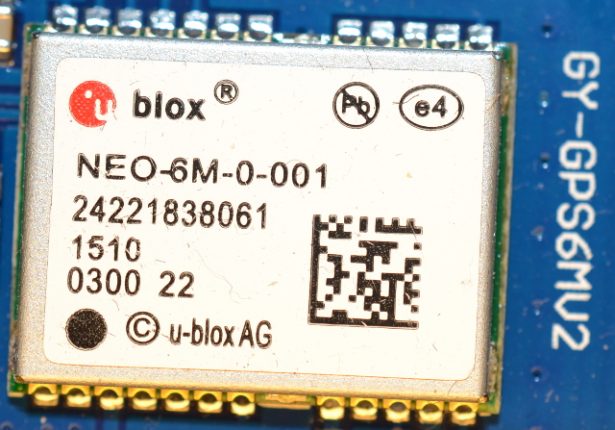
In this article I’m using a different GPS module than I did in the previous articles. The baud rate is 9600, so I have to configure the uart port to match this. To read out the time, I’m going to use the GPRMC sentence. This sentence looks like this:
$GPRMC,161229.487,A,3723.2475,N,12158.3416,W,0.13,309.62,120598,,*10
The GPRMC sentence and others are sent each second. The software will search for the right one and use the information from that.
Hardware
The following schematic is built on a breadboard. Notice the display LCD output block. D6 and D7 are connected to the PICs pins 12 and 13. This happens to be PGC and PGD, the programming pins. I’m not going to read from the LCD, so I ground the RW pin. I’ve also grounded D0-D3. It is good practice to ground unused pins like this, however unused pins on a PIC mounted on a PCB I like to route to a pad for easy access if I’m adding some more features to the project. This is not the case here since the circuit is breadboarded.
Parts List
The following is an edited list from the BOM ulp in EagleCAD.
Software
The software is commented, but I’ll walk through it in general here.
First are the includes libraries, configuration bits, variable declaration, and prototyping of the functions. Then I have the functions to drive the LCD display. To get the LCD display to work properly, you’ll have to follow a certain recipe. After that comes the uart functions and two functions to display a message when the received time and date is not valid.
The main program starts off with some instructions: turning off comparators, setting the right directions to the ports, and set all port s to low. Then it initialize the LCD port and the uart port. In the main while-loop, each byte received on RX is placed in a variable. The variable is compared to see if it’s the dollar sign, $. If it is a dollar sign, I know now that I’m at the beginning of an NMEA sentence, but I don’t know which one. Then it reads the next six bytes and puts them in an array. This array is then compared to a predefined array. If it is equal, then I know two things: one, I have a sentence and two, I have the right sentence. Now follows a lot of for-loops, to read and place the right values in the right places. In this example it reads time, date, latitude and longitude, but only time and date are displayed on the LCD.
When the program is near the end of the main while-loop, it displays the time and date on the LCD. The time displayed is often called GPS ZULU time.
You can download the c-source code below.
Conclusion
In this article, I’ve shown you one way to get the time and date from a GPS module using a PIC microcontroller. With small changes in the code, you can use this on a different PIC. The program reads time, date, latitude and longitude, but it only display the time and date. I challenge the reader to display lat and lon.
Pictures and Video
Here are some pictures of the breadboard.
