Introduction
Our project was an EEG-controlled brain computer interface that allowed a user to correct errors in machine behavior. The project was modeled as a trial-based “game.” In each trial, a solid colored green block or dotted yellow block was placed on a conveyor belt. One end of the conveyor belt had a solid colored green box and the other end had a dotted yellow box. It was the user’s goal to get the block to move to the side of its corresponding patterned/colored box. In each trial of the game, the conveyor belt began to move in a randomly chosen direction. If the random direction was correct, the user needed to stay calm in order to allow the block to travel fully to the correct side and fall into its collection bucket. If the random direction was incorrect, the user needed to attempt to correct the direction by spiking their anxiety as determined by data from an EEG headband.
Design
The initial conception of our project can be attributed to our general interest in EEG-controlled robotics. Upon research in this topic, we came across work done at MIT’s Computer Science and Artificial Intelligence Laboratory regarding robot control using brainwaves and hand gestures. Our intent was to take inspiration from this research and demonstrate that we could create a consumer-friendly, inexpensive, EEG-controlled error correction interface with a timeline of five weeks.
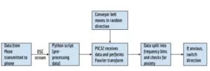
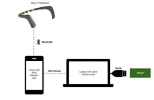
To make this product consumer-friendly, we used the Muse 2 as our EEG headband. The Muse 2 has seven EEG electrodes, with the four main electrodes located on the forehead and behind the ears, and three additional reference sensors. The Muse 2 headband was donated to us by the Salk Institute in San Diego. First, data was sent over Bluetooth from the Muse headband to a phone. Then, the data was transmitted via OSC (Open Sound Control) to a computer. This data path was necessary due to the budget constraints and additional hardware necessary to receive Bluetooth data directly on a laptop. Then, the data was sent over serial to the PIC32, and an FFT was performed on the data (Figure 2). The conveyor belt moved in a random direction to start the game. Once the FFT was performed, we checked for anxiety spikes, and if the user was anxious, the conveyor belt switched directions. Figure 1 shows a block diagram of the system.
The OSC stream protocol worked by transmitting an OSC packet to an OSC server through either TCP (Transmission Control Protocol) or UDP (User Datagram Protocol), which are both IP based protocols. In this lab, we used UDP because if small sections of the data were not transmitted correctly, we could throw out the data and still obtain the correct result. This also simplified the code because UDP did not require the user to recognize when the data was received. UDP is specified by the Internet Engineering Task Force (IETF) via STD 6: User Datagram Protocol. This standard explains how application programs can send messages to other programs via a transaction oriented protocol.
Hardware
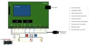
Figure 3 shows a wiring diagram.
Our hardware design was broken up into 3 parts: serial hardware, motor control hardware, and game play hardware.
Serial:
For serial, we used the serial-USB cable. The UART receive pin (U2RX) was wired to RA1 on the board and the UART transmission pin (U2TX) was wired to RB10 on the board. Additionally, the serial-USB cable was grounded to the MCU ground, and the USB Vcc was not wired to anything.
Motor Control Hardware:
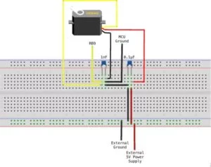
For the motor, we used a continuous rotation parallax servo. Since DC motors can cause inductive spikes that can blow out the transistors on the board, we used capacitors to reduce any chance of inductive spikes. We connected a 0.1 μF capacitor across the external 5V power supply and ground, and then a 1 nF capacitor across ground and the signal wire of the servo. The signal wire was connected to OC3, which is mapped to RPB9 (pin 18) on the board.
Game Play Hardware:
The game play hardware consisted of 3 buttons and 3 LEDs. The 3 buttons corresponded to start game (grey button), correct bin (blue button), and incorrect bin (red button). The start game button was wired to RA2 on the board and ground, the correct bin button was wired to RA3 on the board and ground, and the incorrect bin button was wired to RA4 on the board and ground. The LEDs corresponded to whether or not the player got the block in the correct bin as well as which bin was correct.
Mechanical Design
We had several design considerations before mechanical construction of our conveyor belt.
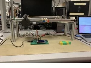
Because eye movement is observed on EEG measurements, we ensured that the horizontal length of the conveyor belt was relatively short (~12 inches) so that when the user’s eyes followed the traveling blocks, the EEG data would remain unaffected. Additionally, we picked a continuous rotational servo with low torque (38 oz-in) due to the fact that we did not need the belt to move at a high speed. Knowing that our project required lots of iterative testing, we chose to use 2020 aluminum T slot tracks as the material for the frame for our conveyor belt for durability and universal hardware mounting. Lastly, we used multiple rubber bands as the belt to keep our budget minimized and to allow for easy replacement during testing.
We made a 3D model of the conveyor belt that we intended to construct (Figure 6). Using this model and our design considerations, we assembled our conveyor belt (Figure 7).
Software
Our software for the PIC was broken down into 2 functions, FFT function and change_direction function, and 4 threads, the timer thread, motor thread, serial thread, and FFT thread, as well as an ISR. We also had a python script that sent data from the headband to the PIC over serial. On a high level, data was received in the serial thread from the python script running on a computer. In the serial thread, raw EEG data was placed into arrays and pre-FFTed data from the Muse itself was saved into single variables. Once an array of raw sensor data was full, the array was run through an FFT in order to update a running average of baseline EEG activity. In the motor thread, the pre-FFTed data was compared to this running average and, if the pre-FFTed data was much greater than the baseline, the motor thread determined that an anxiety spike was occuring. This changed the direction of the conveyor belt if a trial of a game was actively occurring. The details of each part of our software are explained below.
FFT Function:
For the FFT function, we used Bruce’s FFT algorithm from the FFT spectrum analyzer with TFT-LCD output. This function was optimized for use with fixed point numbers. We performed FFTs on arrays of size 256, so we defined N_WAVE as 256 and LOG2_N_WAVE as 8. This function returned an average of the magnitudes of all FFT bins in order to update our running average of baseline EEG activity which was used in other threads to determine anxiety spikes. To obtain this average, we added the power magnitude of all frequency bins together and divided by 128. The rest of this algorithm was consistent with Bruce’s implementation.
Change Direction Function:
This function set the duration of the PWM for the servo motor. The PWM signal was updated using this duration in the ISR. We changed the pulse width using a variable we called duration, and we used a switch statement using a variable called direction, where 0 corresponds to stop, 1 corresponds to counterclockwise rotation, and 2 corresponds to clockwise rotation. When direction was 0, the duration was set to 12000. When direction is 1, the duration was 12100, and when the direction was 2, the duration was set to 11900. These numbers were determined based on trial and error tuning of our specific servo motor.
Timer Thread:
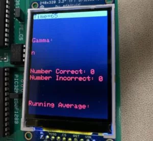
The timer thread printed the time since reset at the top of the TFT. We kept track of time in order to determine when we believed we had enough baseline EEG data to begin playing the game (we typically had enough data about a minute after transmission began).
Motor Thread:
The motor thread controlled the motor and game play. First, we read the values from port A, bits 2, 3, and 4, which corresponded to the 3 buttons. The values read-in on these pins determined whether we were starting a trial, completing a trial when the correct outcome had occurred, or completing a trial when the incorrect outcome had occurred. We also saved the current state of the game and the previous state of the game, in order to determine whether we should complete actions that were only supposed to be carried out at the beginning of each round. When the start game button was low (meaning the button was pressed), we set valid_round high and score_incremented low. Score_incremented ensured that the score was only incremented one time per round even if the buttons were pressed more than once. We also printed “Start Game” so that the user would know that the game had started. Then, if either button_right or button_wrong went low at any point, we set valid_round equal to 0 to signal that the game had ended. We also increment the number_right or number_wrong based on which button was pressed and printed the updated scores. If button_right was pressed, we lit up an LED corresponding to the color of the collection bucket based on the direction that the conveyor belt was moving when the game completed. If button_wrong was pressed, we lit up a red LED in the middle of the conveyor belt to signal that the block landed in the incorrect bin. The next section of the thread checked if there was a valid round occurring. If a valid round was occuring, and it was the first cycle in this valid round (as determined by comparing valid_round to its previous value), we started the conveyor belt in a random direction from a randomly generated seed based on the current time. We compared our gamma value (from the pre-FFT data) to our running average from the FFTed raw data, as completed in the FFT thread. If the gamma value was at least 0.2 higher than the running average for 4 cycles, then we considered this an “anxiety event”. After an anxiety event was detected, it took 3 cycles of gamma data below the threshold for the debouncer to consider the EEG activity “not an anxiety event”. This ensured that the user had actually calmed down, instead of the PIC just receiving a transmission error. If there was not a valid game, meaning that the “correct” or “incorrect” end game buttons had been pressed, we set direction of the conveyor belt equal to zero and called change_direction(0) so the conveyor belt stopped. We also updated change, previous_change and the debounce counters to be ready for the next round.
Serial Thread:
The serial thread saved both the raw data and the pre-FFT data sent from the headband via the python script. The python script sent data every time it received an exclamation point. We used the thread PT_DMA_PutSerialBuffer, because this function used DMA for serial communication, which was fast. To use this thread, we spawned a child thread, which blocked the serial thread from executing while PT_DMA_PutSerialBuffer was executing. Next, we used PT_GetMachineBuffer to get the data from the python script. We used PT_GetMachineBuffer so that the data could be sent without a user inputting any data. We used a termination time of 5 seconds and a termination character count of 5 characters. If we received data, we scanned PT_term_buffer and saved the data value into cmd and its tag into a variable called value2. The tag indicated whether we were receiving raw data or pre-FFTed data, as well as which sensor the data was being received from in the case of raw data. If we do not receive anything, we set cmd to 0. Then, we divided cmd by 1000 and checked to see if it was less than 0.1 or greater than 0.999 to ensure that the values were in the correct range. If they were not in the correct range, meaning we received corrupted data, we set the value of cmd equal to its previous value. Though this caused us to lose some accuracy, we took this approach because EEG readings do not tend to change very quickly, and the timing of our system was slightly more important than making sure every data point was exactly correct. Then, we had a switch statement based on the value2 tag to save the data into the correct variables. Case ‘1’ was our gamma values (pre-FFTed values from the Muse headband), so we saved cmd into the variable ‘gam’. We ultimately decided to only save raw data from the two Muse sensors located on the forehead because these were the 2 main sensors associated with collecting data for gamma waves. Each of these sensors had two arrays. While one array was being filled, there was an FFT being performed on the other array. To ensure that we were filling the correct array, we use the variable ‘lock’ to indicate which array should be filled, and changed this value once the FFT had been performed. We also had counters for each sensor so that we ensured that we were filling in the correct index and that the array was full before we performed an FFT on it. Case ‘7’ was our AF7 sensor, so we saved the value into the respective array based on lock. If lock was equal to 1, this meant that there was an FFT being performed on F1af7 and F1af8, so we put cmd multiplied by the window into F2af7 at ctr3, which is the counter for the AF7 sensor. If lock was equal to 0, there was an FFT being performed on F2af7 and F2af8, so we put cmd multiplied by the window (initialized in main) into F1af7 at cr3. Lastly, we incremented ctr3 if it was less than 255, since the size of F1af7 andF2af7 was 256. Case ‘8’ was our AF8 sensor, so we saved the value into the respective array based on the lock. If lock was equal to 1, this meant that there was an FFT being performed on F1af7 and F1af8, so we put cmd multiplied by the window (initialized in main) into F2af8 at ctr4, which was the counter for the AF8 sensor. If lock was equal to 0, there was an FFT being performed on F2af7 and F2af8, so we put cmd multiplied by the window into F1af8 at ctr4. Lastly, we incremented ctr4 if it was less than 255, since the size of F1af8 and F2af8 was 256.
FFT Thread:
The FFT thread first checked if either set of raw data arrays contained 256 data points. If a set of arrays was full, it would call the FFT function on the filled arrays while allowing the other, unfilled arrays to be used in the serial thread to collect data. Once the FFT function was complete, all FFT bins were averaged together, and this average was used to update the running average baseline for anxiety thresholding. The running average was then printed at the bottom of the TFT display.
ISR:
The ISR changed the motor direction by adjusting the length of the PWM pulse. The desired motor direction was set in the Motor Thread.
Main:
In main, we initialized all of the threads and scheduled them based on round robin scheduling. We also initialized the motor and set the input pins. Additionally, we created the sine lookup table and the window array to help scale the data values to the correct range.
Python Script:
The python script first set up a server to receive the OSC stream from a phone. The phone was connected over bluetooth to the Muse Headband to receive both the raw data and the pre-FFT data. Once this server was established, methods were added to the server in order to receive data from specific transmission channels (i.e. in order to receive specifically from the raw sensor data channel or specifically from the gamma frequency data channel). These methods added the received data to predetermined queues, either the gamma queue or a raw sensor queue, given that the data actually contained a number as expected (instead of just garbage). Once the methods were added to the server, serial communication was established with the PIC32. We then used a multithreaded python script in order to receive OSC data and add it to queues, while simultaneously preprocessing and truncating some significant figures and sending this data with an appropriate tag over serial to the PIC32. We added character tags to all of our serial transmissions in case we could not guarantee the order of data transmission. For our analysis, it was important to identify whether we were sending pre-FFTed or raw data, as well as which sensor the raw data originated from.
Testing and Results
We first tested our ability to communicate over serial. Our original implementation of serial caused us to get a large amount of unexpected and inaccurate data on the PIC32. To remedy this, we decided to only send data when the PIC32 was ready to receive, as indicated by it sending an exclamation point over serial to the computer. We then noticed that our serial communication was hanging at random times. To fix this, we went into the protothread header files and cleared all serial errors each time a read or write was performed. This solved many of the hanging problems, yet we still could not reliably establish communication for more than about five minutes. We then began to flush the serial buffer in the python script, as well as lock our python thread whenever we performed a read/write, which finally fully fixed the problem and allowed us to communicate for hours at a time.
We then noticed that, despite having a baud rate of 115200, we were becoming massively delayed in our serial transmission and creating queues of steadily increasing size so that any data sent was actually delayed from real-time by thousands of data points. Because our project relied so heavily on quick responses to fairly noisy data, we decided to average together three data points in the server methods before adding data to a queue. This allowed us to keep up with transmission and keep our queue size between 1 and 0 at all times.
Once each thread functioned as desired and all data was properly transmitted, we began to analyze speed and performance. Given the size of our FFT, we ultimately ended up updating our running average about every 3 seconds. This was an appropriate rate given that the average should not rapidly change from millisecond to millisecond, but instead should hold as a fairly steady baseline once the program had been running long enough to collect several data points. We then analyzed our speed in receiving the pre-FFTed gamma data. We updated this data slightly faster, about once every half second, allowing for many data points to be received during any given trial of the game. Because of this data rate, we adjusted our conveyor belt to move fairly slowly. This allowed for appropriate debouncing of anxiety spikes and ample time for users to respond to the conveyor belt motion in order to correct errors.
We then focused on thresholding. In order to achieve clean results, we added a debouncing component to detecting anxiety spikes. For activity to be called an anxiety spike, an anxiety state needed to be held for four data points. Similarly, in order for a spike to be marked as complete, activity would need to be below the threshold for more than 2 data points. The threshold was determined by trial and error. However, by using the running average of all FFTed data as the baseline for this threshold, the game was relatively transferable to different players. If a player had a higher baseline, they would need to cause a higher spike in order for an anxiety event to occur. After tuning the threshold, we found that our accuracy in getting blocks into correct bins was over 90% for data taken from one player over about 60 trials. We are interested in further investigating this accuracy for different players, as well as taking more structured data for the original player. A video of our early testing can be seen below:
To test motor control, we programmed a PWM signal to output on RB9 (using a timer-based ISR), and used an oscilloscope to see the duration of the pulses and how far apart the pulses were. For continuous rotation servos, the length of a pulse determines the stop, clockwise, and counterclockwise rotation. A decrease in the pulse width causes the servo to rotate faster in the clockwise direction, and an increase in the pulse width causes faster rotation in a counterclockwise direction. We tuned our servo to rotate at a desired slow speed by changing the duration of pulses in our code.

Conclusion
Through the completion of this project, we were able to design, build, and demonstrate machine error corrections in real time using EEG signals. Our design generally met our expectations. We were highly satisfied with our data analysis abilities and the cleanness with which we could ultimately label anxiety spikes. We were slightly disappointed in the mechanical performance of our conveyor belt, and would have liked to rebuild it given more time. In terms of future improvements, we would like to add a learning component to our game. If a user marks a trial as wrong, we would like to have functionality which can adjust our thresholding to reduce the likelihood of an incorrect round in the future. We would also like to further investigate how EEG data can be used in human-machine interactions, maybe by feeding EEG data into neural networks to see whether we could discriminate thoughts such as “left” or “right.” However, given the time and budget constraints in this project, we believe we created a robust project which successfully met nearly all of our expectations.
Our final product met the general standards for this course as it had more than 50% of its data processing on the PIC32 (raw sensor FFT, thresholding, and spike-debouncing was done on the PIC32 whereas only specifically gamma-band FFTs were done elsewhere). All game-play and motor logic was also implemented on the PIC32. The design was under-budget (see Appendix C), and our group spent a large amount of time in-lab working to make sure each individual component of the hardware and software performed robustly.
This project used the Muse 2 EEG headband, and used the Mind Monitor app in order to receive the raw sensor data and pre-FFTed gamma data over OSC. The python written for this report was based on the open-source project, “Telekinesis Car,” created by Devin Delfino. The link to the Github repository containing the code for this project is linked in the reference section of the report.
Our design was very safe. The only component attached to a physical person was the EEG headband, which is commercially available and powered by a charged battery. It also sends data over bluetooth, so there are no extraneous wires attached to any person. Additionally, The conveyor belt was built from sturdy material, and the servo was strongly attached to the conveyor belt, so no parts were at risk of coming loose. Our design also had accessibility considerations. We chose yellow and green as our block colors, and dotted our yellow blocks/bin, in order to be accessible to those who are color blind.
We therefore believe we are in compliance with the IEEE code of ethics. Our project did not endanger the environment or any person who actively used the game. We do not have any conflicts of interest, did not fabricate any performance data, and did not participate in bribery of any kind. We have fully credited contributors to each part of this project, and we believe that our project beneficially highlights the growing potential and promise of EEG-based human-computer interfaces.
Commented Code
EEG data receiving, FFT, and motor control:
| /* | |
| * File: TFT, keypad, DAC, LED, PORT EXPANDER test | |
| * With serial interface to PuTTY console | |
| * Author: Rebecca Bell, Emma Kaufman, Chloe Kuo, Bruce Land | |
| * For use with Sean Carroll’s Big Board | |
| * http://people.ece.cornell.edu/land/courses/ece4760/PIC32/target_board.html | |
| * Target PIC: PIC32MX250F128B | |
| */ | |
| //////////////////////////////////// | |
| // clock AND protoThreads configure! | |
| // You MUST check this file! | |
| // TEST OLD CODE WITH NEW THREADS | |
| //#include “config_1_2_3.h” | |
| #include “config_1_3_2.h“ | |
| // threading library | |
| //#include “pt_cornell_1_2_3.h” | |
| #include “pt_cornell_1_3_2.h“ | |
| // yup, the expander | |
| #include “port_expander_brl4.h“ | |
| //////////////////////////////////// | |
| // graphics libraries | |
| // SPI channel 1 connections to TFT | |
| #include “tft_master.h“ | |
| #include “tft_gfx.h“ | |
| // need for rand function | |
| #include <stdlib.h> | |
| // need for sin function | |
| #include <math.h> | |
| #include <string.h> | |
| #include <stdlib.h> | |
| #include <stdio.h> | |
| //////////////////////////////////// | |
| // lock out timer 2 interrupt during spi comm to port expander | |
| // This is necessary if you use the SPI2 channel in an ISR. | |
| // The ISR below runs the DAC using SPI2 | |
| #define start_spi2_critical_section INTEnable(INT_T2, 0) | |
| #define end_spi2_critical_section INTEnable(INT_T2, 1) | |
| //////////////////////////////////// | |
| /* Demo code for interfacing TFT (ILI9340 controller) to PIC32 | |
| * The library has been modified from a similar Adafruit library | |
| */ | |
| // Adafruit data: | |
| /*************************************************** | |
| This is an example sketch for the Adafruit 2.2″ SPI display. | |
| This library works with the Adafruit 2.2″ TFT Breakout w/SD card | |
| —-> http://www.adafruit.com/products/1480 | |
| Check out the links above for our tutorials and wiring diagrams | |
| These displays use SPI to communicate, 4 or 5 pins are required to | |
| interface (RST is optional) | |
| Adafruit invests time and resources providing this open source code, | |
| please support Adafruit and open-source hardware by purchasing | |
| products from Adafruit! | |
| Written by Limor Fried/Ladyada for Adafruit Industries. | |
| MIT license, all text above must be included in any redistribution | |
| ****************************************************/ | |
| // === the fixed point macros ======================================== | |
| typedef signed short fix14 ; | |
| #define multfix14(a,b) ((fix14)((((long)(a))*((long)(b)))>>14)) //multiply two fixed 2.14 | |
| #define float2fix14(a) ((fix14)((a)*16384.0)) // 2^14 | |
| #define fix2float14(a) ((float)(a)/16384.0) | |
| #define absfix14(a) abs(a) | |
| // === input array size for FFTs ======================================= | |
| #define N_WAVE 256 | |
| // string buffer for serial | |
| char buffer[60]; | |
| //////////////////////////////////// | |
| // DAC ISR | |
| // A-channel, 1x, active | |
| #define DAC_config_chan_A 0b0011000000000000 | |
| // B-channel, 1x, active | |
| #define DAC_config_chan_B 0b1011000000000000 | |
| //PORT A | |
| #define EnablePullDownA(bits) CNPUACLR=bits; CNPDASET=bits; | |
| #define DisablePullDownA(bits) CNPDACLR=bits; | |
| #define EnablePullUpA(bits) CNPDACLR=bits; CNPUASET=bits; | |
| #define DisablePullUpA(bits) CNPUACLR=bits; | |
| // PORT B | |
| #define EnablePullDownB(bits) CNPUBCLR=bits; CNPDBSET=bits; | |
| #define DisablePullDownB(bits) CNPDBCLR=bits; | |
| #define EnablePullUpB(bits) CNPDBCLR=bits; CNPUBSET=bits; | |
| #define DisablePullUpB(bits) CNPUBCLR=bits; | |
| //== Timer 2 interrupt handler =========================================== | |
| volatile SpiChannel spiChn = SPI_CHANNEL2 ; // the SPI channel to use | |
| volatile int spiClkDiv = 4 ; // 10 MHz max speed for port expander!! | |
| // Sine Table for FFT | |
| #define sine_table_size 256 | |
| volatile int sin_table[sine_table_size]; | |
| int sum = 0; | |
| int ctr1, ctr2, ctr3, ctr4; //variables to ensure only full arrays get FFTed | |
| int print_counter = 0; | |
| fix14 F1tp9[256], F2tp9[256]; //arrays to hold raw sensor data | |
| fix14 F1tp10[256], F2tp10[256]; | |
| fix14 F1af7[256],F2af7[256]; | |
| fix14 F1af8[256], F2af8[256]; | |
| float beta; //variables to hold pre-FFTed data | |
| float gam; | |
| int lock; //lock to make sure arrays are not overwritten while FFT occurs | |
| int lock_buffer; | |
| float P0, P1; //variables to hold average of FFT bins | |
| int change = 0; //variable to hold whether valid round has just started | |
| float running_avg; //holds running average of FFTed raw sensor data | |
| int avg_lock; //stops lock from updating while a spike occurs (to prevent skew) | |
| fix14 window[N_WAVE]; // a table of window values for the FFT | |
| int button; //variables to hold button reads | |
| int button_success; | |
| int button_fail; | |
| int valid_round = 0; //variable for game logic | |
| int number_right; //score variables | |
| int number_wrong; | |
| float prev_cmd = 0; //variable to use in case garbage transmission over serial | |
| static int duration; | |
| int junk; | |
| void __ISR(_TIMER_2_VECTOR, ipl2) Timer2Handler(void) | |
| { | |
| mT2ClearIntFlag(); | |
| SetDCOC3PWM(duration); //update PWM (servo direction) | |
| junk = ReadSPI2(); | |
| } | |
| // === print a line on TFT ===================================================== | |
| // print a line on the TFT | |
| // string buffer | |
| char buffer[60]; | |
| void printLine(int line_number, char* print_buffer, short text_color, short back_color){ | |
| // line number 0 to 31 | |
| /// !!! assumes tft_setRotation(0); | |
| // print_buffer is the string to print | |
| int v_pos; | |
| v_pos = line_number * 10 ; | |
| // erase the pixels | |
| tft_fillRoundRect(0, v_pos, 239, 8, 1, back_color);// x,y,w,h,radius,color | |
| tft_setTextColor(text_color); | |
| tft_setCursor(0, v_pos); | |
| tft_setTextSize(1); | |
| tft_writeString(print_buffer); | |
| } | |
| void printLine2(int line_number, char* print_buffer, short text_color, short back_color){ | |
| // line number 0 to 31 | |
| /// !!! assumes tft_setRotation(0); | |
| // print_buffer is the string to print | |
| int v_pos; | |
| v_pos = line_number * 20 ; | |
| // erase the pixels | |
| tft_fillRoundRect(0, v_pos, 239, 16, 1, back_color);// x,y,w,h,radius,color | |
| tft_setTextColor(text_color); | |
| tft_setCursor(0, v_pos); | |
| tft_setTextSize(2); | |
| tft_writeString(print_buffer); | |
| } | |
| // === thread structures ============================================ | |
| // thread control structs | |
| // note that UART input and output are threads | |
| static struct pt pt_timer, pt_fft, pt_serial, pt_motor ; | |
| // The following threads are necessary for UART control | |
| static struct pt pt_input, pt_output, pt_DMA_output ; | |
| void change_direction(int dir) { | |
| switch (dir) { | |
| case 0: // stop | |
| duration = 12000; | |
| break; | |
| case 1: // ccw | |
| duration = 12100; | |
| break; | |
| case 2: // clockwise | |
| duration = 11900; | |
| break; | |
| } | |
| } | |
| static PT_THREAD(protothread_motor(struct pt *pt)) { | |
| PT_BEGIN(pt); | |
| static int debounce_high = 0; //debouncing variables for anxiety spikes | |
| static int debounce_low; | |
| static int previous_change = 0; //variable to keep track of whether valid round has just started | |
| static int direction = 0; //servo direction | |
| static int score_incremented = 0; //variable to keep track of whether score has been changed yet | |
| static int previous_round = 0; //variable to keep track of whether a random number should be generated for direction | |
| static int temp_dir; //for random number generation | |
| sprintf(buffer, “Number Correct: %i“, number_right); //print score | |
| printLine2(9, buffer, 0xF800, 0x0000); | |
| sprintf(buffer, “Number Incorrect: %i“, number_wrong); | |
| printLine2(10, buffer, 0xF800, 0x0000); | |
| while(lock_buffer) { | |
| button = mPORTAReadBits(BIT_2); //read buttons | |
| button_success = mPORTAReadBits(BIT_4); | |
| button_fail = mPORTAReadBits(BIT_3); | |
| previous_round = valid_round; | |
| if (!button) { //start game if start button is pushed | |
| valid_round = 1; | |
| score_incremented = 0; | |
| sprintf(buffer, “Start Game“); | |
| printLine2(8, buffer, 0xF800, 0x0000); | |
| } | |
| if (!button_success || !button_fail){ //change score and end game if any other button is pushed | |
| valid_round = 0; | |
| sprintf(buffer, ““); | |
| printLine2(8, buffer, 0xF800, 0x0000); | |
| if (!button_success && !score_incremented) { | |
| number_right++; | |
| score_incremented = 1; | |
| sprintf(buffer, “Number Correct: %i“, number_right); | |
| printLine2(9, buffer, 0xF800, 0x0000); | |
| if (direction == 1) { | |
| change_direction(0); | |
| direction = 0; | |
| mPORTBToggleBits(BIT_13); //flash appropriate LED based on direction | |
| PT_YIELD_TIME_msec(500); | |
| mPORTBToggleBits(BIT_13); | |
| PT_YIELD_TIME_msec(500); | |
| mPORTBToggleBits(BIT_13); | |
| PT_YIELD_TIME_msec(500); | |
| mPORTBToggleBits(BIT_13); | |
| PT_YIELD_TIME_msec(500); | |
| mPORTBToggleBits(BIT_13); | |
| PT_YIELD_TIME_msec(500); | |
| mPORTBToggleBits(BIT_13); | |
| } | |
| else{ | |
| change_direction(0); | |
| direction = 0; | |
| mPORTBToggleBits(BIT_7); | |
| PT_YIELD_TIME_msec(500); | |
| mPORTBToggleBits(BIT_7); | |
| PT_YIELD_TIME_msec(500); | |
| mPORTBToggleBits(BIT_7); | |
| PT_YIELD_TIME_msec(500); | |
| mPORTBToggleBits(BIT_7); | |
| PT_YIELD_TIME_msec(500); | |
| mPORTBToggleBits(BIT_7); | |
| PT_YIELD_TIME_msec(500); | |
| mPORTBToggleBits(BIT_7); | |
| } | |
| } | |
| else if (!score_incremented) { | |
| number_wrong++; | |
| score_incremented = 1; | |
| sprintf(buffer, “Number Incorrect: %i“, number_wrong); | |
| printLine2(10, buffer, 0xF800, 0x0000); | |
| change_direction(0); | |
| direction = 0; | |
| mPORTBToggleBits(BIT_15); //flash appropriate LED based on wrong outcome | |
| PT_YIELD_TIME_msec(500); | |
| mPORTBToggleBits(BIT_15); | |
| PT_YIELD_TIME_msec(500); | |
| mPORTBToggleBits(BIT_15); | |
| PT_YIELD_TIME_msec(500); | |
| mPORTBToggleBits(BIT_15); | |
| PT_YIELD_TIME_msec(500); | |
| mPORTBToggleBits(BIT_15); | |
| PT_YIELD_TIME_msec(500); | |
| mPORTBToggleBits(BIT_15); | |
| } | |
| } | |
| if (valid_round) { | |
| if (!previous_round) { //generate random direction for each round | |
| srand((int) PT_GET_TIME()); | |
| temp_dir = rand(); | |
| if (temp_dir < 1000000000) | |
| direction = 1; | |
| else | |
| direction = 2; | |
| change_direction(direction); | |
| previous_change = 0; | |
| change = 0; | |
| } | |
| previous_change = change; | |
| sprintf(buffer, “%3f“, gam); | |
| printLine2(5, buffer, 0xF800, 0x0000); | |
| if ((gam) > running_avg*10+.3){ //looko for anxiety spikes | |
| debounce_high ++; | |
| debounce_low = 0; | |
| if (change == 0 && debounce_high > 4){ //only declare anxiety spike if above threshold for more than 4 points | |
| avg_lock = 1; | |
| sprintf(buffer, “a“); | |
| printLine2(6, buffer, 0xF800, 0x0000); | |
| debounce_high = 0; | |
| change = 1; | |
| if (previous_change != change) { //if there is an anxiety spike, change directions | |
| if (direction == 1) { | |
| change_direction(2); | |
| direction = 2; | |
| } | |
| else if (direction == 2) { | |
| change_direction(1); | |
| direction = 1; | |
| } | |
| } | |
| } | |
| } | |
| else { | |
| debounce_low ++; | |
| debounce_high = 0; | |
| if (change == 1 && debounce_low > 2){ //if data is below threshold for more than two points, say spike is over | |
| avg_lock = 0; | |
| sprintf(buffer, “n“); | |
| printLine2(6, buffer, 0xF800, 0x0000); | |
| debounce_low = 0; | |
| change = 0; | |
| } | |
| } | |
| } | |
| else { | |
| change = 0; | |
| debounce_high = 0; | |
| debounce_low = 0; | |
| sprintf(buffer, “n“); | |
| printLine2(6, buffer, 0xF800, 0x0000); | |
| } | |
| PT_YIELD_TIME_msec(1000); | |
| } | |
| PT_END(pt); | |
| } | |
| // system 1 second interval tick | |
| int sys_time_seconds ; | |
| // === Timer Thread ================================================= | |
| // update a 1 second tick counter | |
| static PT_THREAD (protothread_timer(struct pt *pt)) | |
| { | |
| PT_BEGIN(pt); | |
| // set up LED to blink | |
| mPORTASetBits(BIT_0 ); //Clear bits to ensure light is off. | |
| mPORTASetPinsDigitalOut(BIT_0 ); //Set port as output | |
| while(lock_buffer) { | |
| // yield time 1 second | |
| PT_YIELD_TIME_msec(1000) ; | |
| sys_time_seconds++ ; | |
| // toggle the LED on the big board | |
| mPORTAToggleBits(BIT_0); | |
| // draw sys_time | |
| sprintf(buffer,“Time=%d“, sys_time_seconds); | |
| printLine2(0, buffer, ILI9340_BLACK, ILI9340_YELLOW); | |
| // NEVER exit while | |
| } // END WHILE(1) | |
| PT_END(pt); | |
| } // timer thread | |
| //=== Serial terminal thread ================================================= | |
| static PT_THREAD (protothread_serial(struct pt *pt)) | |
| { | |
| PT_BEGIN(pt); | |
| static float cmd[30]; | |
| static char value2[30]; | |
| while(1) { | |
| // send the prompt via DMA to serial | |
| //cursor_pos(4,1); | |
| //red_text ; | |
| lock_buffer=0; | |
| sprintf(PT_send_buffer,“!“); //send exclamation point to indicate PIC is ready to receive data | |
| // by spawning a print thread | |
| PT_SPAWN(pt, &pt_DMA_output, PT_DMA_PutSerialBuffer(&pt_DMA_output) ); | |
| lock_buffer = 1; | |
| //clr_right ; | |
| //normal_text ; | |
| //spawn a thread to handle terminal input | |
| // the input thread waits for input | |
| // — BUT does NOT block other threads | |
| // string is returned in “PT_term_buffer” | |
| // !!!! — !!!! | |
| // Choose ONE of the following: | |
| // PT_GetSerialBuffer or PT_GetMachineBuffer | |
| // !!!! — !!!! | |
| //PT_SPAWN(pt, &pt_input, PT_GetSerialBuffer(&pt_input) ); | |
| // | |
| // PT_GetMachineBuffer assumes a input | |
| // from a module, like GPS or Bluetooth | |
| // Terminate on <enter> key | |
| // PT_terminate_char = ‘\r’ ; | |
| // PT_terminate_count = 0 ; | |
| // PT_terminate_time = 0 ; | |
| // — | |
| // Terminate on ‘#’ key | |
| // PT_terminate_char = ‘#’ ; | |
| // PT_terminate_count = 0 ; | |
| // PT_terminate_time = 0 ; | |
| // — | |
| // Terminate after exactly 5 characters | |
| // or | |
| // Terminate after 5 seconds | |
| PT_terminate_char = 0 ; | |
| PT_terminate_count = 5 ; | |
| PT_terminate_time = 5 ; | |
| // note that there will NO visual feedback using the following function | |
| //lock_buffer = 0; | |
| PT_SPAWN(pt, &pt_input, PT_GetMachineBuffer(&pt_input) ); | |
| //lock_buffer = 1; | |
| // returns when the thead dies on the termination condition | |
| // IF using PT_GetSerialBuffer, when <enter> is pushed | |
| // IF using PT_GetMachineBuffer, could be on timeout | |
| if(PT_timeout==0) { | |
| sscanf(PT_term_buffer, “%f %s“, cmd, &value2); | |
| //sum = sum + cmd[0]; | |
| //sum_count++; | |
| //sprintf(PT_send_buffer,”!”); | |
| // by spawning a print thread | |
| //PT_SPAWN(pt, &pt_DMA_output, PT_DMA_PutSerialBuffer(&pt_DMA_output) ); | |
| } | |
| // no actual string | |
| else { | |
| // uncomment to prove time out works | |
| //mPORTAToggleBits(BIT_0); | |
| // disable the command parser below | |
| cmd[0] = 0 ; | |
| } | |
| cmd[0] = cmd[0]/1000; | |
| if (cmd[0] < 0.1) { //make sure valid data is received. If not, replace it | |
| cmd[0] = prev_cmd; | |
| } | |
| if (cmd[0] > 1) { | |
| cmd[0] = .999; | |
| } | |
| prev_cmd = cmd[0]; | |
| //lock_buffer = 1; | |
| //sprintf(buffer,”%i”,sum); | |
| //printLine2(10,buffer, 0xF800, 0x0000); | |
| //sprintf(buffer,”%s”,value2); | |
| //printLine2(12,buffer, 0xF800, 0x0000); | |
| switch(*value2){ | |
| case ‘9‘: | |
| beta = cmd[0]; //save beta data | |
| break; | |
| case ‘1‘: | |
| gam = cmd[0]; //save gamma data | |
| break; | |
| case ‘7‘: | |
| if (lock) //put raw sensor data into correct array (array not being FFTed) | |
| F2af7[ctr3] = multfix14(float2fix14(cmd[0]),window[ctr3]); | |
| else | |
| F1af7[ctr3] = multfix14(float2fix14(cmd[0]),window[ctr3]); | |
| if (ctr3 < 255) //just wait if the other array is still being FFTed | |
| ctr3++; | |
| break; | |
| case ‘8‘: | |
| if (lock) //put raw sensor data into correct array (array not being FFTed) | |
| F2af8[ctr4] = multfix14(float2fix14(cmd[0]),window[ctr4]); | |
| else | |
| F1af8[ctr4] = multfix14(float2fix14(cmd[0]),window[ctr4]); | |
| if (ctr4 < 255) | |
| ctr4++; | |
| break; | |
| default: | |
| break; | |
| } | |
| // never exit while | |
| } // END WHILE(1) | |
| PT_END(pt); | |
| } // thread 3 | |
| //FFT FUNCTION | |
| #define LOG2_N_WAVE 8 /* log2(N_WAVE) 0 */ | |
| #define begin { | |
| #define end } | |
| fix14 Sinewave[N_WAVE]; // a table of sines for the FFT | |
| fix14 fr[N_WAVE], fi[N_WAVE]; | |
| static fix14 zero_point_4 = float2fix14(0.4) ; | |
| int temp; | |
| static int sample_number ; | |
| void FFTfix(fix14 fr[],fix14 fi[], int m) | |
| //Adapted from code by: | |
| //Tom Roberts 11/8/89 and Malcolm Slaney 12/15/94 [email protected] | |
| //fr[n],fi[n] are real,imaginary arrays, INPUT AND RESULT. | |
| //size of data = 2**m | |
| // This routine does foward transform only | |
| begin | |
| P0 = 0; | |
| P1 = 0; | |
| for (temp = 0; temp < 256; temp++) | |
| fi[temp] = 0; | |
| int mr,nn,i,j,L,k,istep, n; | |
| int qr,qi,tr,ti,wr,wi; | |
| mr = 0; | |
| n = 1<<m; //number of points | |
| nn = n – 1; | |
| /* decimation in time – re-order data */ | |
| for(m=1; m<=nn; ++m) | |
| begin | |
| L = n; | |
| do L >>= 1; while(mr+L > nn); | |
| mr = (mr & (L-1)) + L; | |
| if(mr <= m) continue; | |
| tr = fr[m]; | |
| fr[m] = fr[mr]; | |
| fr[mr] = tr; | |
| //ti = fi[m]; //for real inputs, don’t need this | |
| //fi[m] = fi[mr]; | |
| //fi[mr] = ti; | |
| end | |
| L = 1; | |
| k = LOG2_N_WAVE-1; | |
| while(L < n) | |
| begin | |
| istep = L << 1; | |
| for(m=0; m<L; ++m) | |
| begin | |
| j = m << k; | |
| wr = Sinewave[j+N_WAVE/4]; | |
| wi = -Sinewave[j]; | |
| //wr >>= 1; do need if scale table | |
| //wi >>= 1; | |
| for(i=m; i<n; i+=istep) | |
| begin | |
| j = i + L; | |
| tr = multfix14(wr,fr[j]) – multfix14(wi,fi[j]); | |
| ti = multfix14(wr,fi[j]) + multfix14(wi,fr[j]); | |
| qr = fr[i] >> 1; | |
| qi = fi[i] >> 1; | |
| fr[j] = qr – tr; | |
| fi[j] = qi – ti; | |
| fr[i] = qr + tr; | |
| fi[i] = qi + ti; | |
| end | |
| end | |
| –k; | |
| L = istep; | |
| end | |
| for (sample_number = 0; sample_number < 128; sample_number++) | |
| begin | |
| // get the approx magnitude | |
| fr[sample_number] = abs(fr[sample_number]); //>>9 | |
| fi[sample_number] = abs(fi[sample_number]); | |
| // reuse fr to hold magnitude | |
| fr[sample_number] = max(fr[sample_number], fi[sample_number]) + | |
| multfix14(min(fr[sample_number], fi[sample_number]), zero_point_4); | |
| P0 = P0 + fix2float14(fr[sample_number]); | |
| end | |
| P0 = P0/128; //average all bins | |
| end | |
| #define log_min 0x10 | |
| static PT_THREAD (protothread_fft(struct pt *pt)) | |
| { | |
| PT_BEGIN(pt); | |
| //FOR TESTING FFT | |
| static int f; | |
| static float r = 3.141592*2/512; | |
| static float avg = 0; | |
| static fix14 array[512]; | |
| for (f; f < 512; f++) { | |
| //array2[f] = float2fix14(cos(((float) f)*r)); | |
| array[f] = multfix14(float2fix14(sin(((float) f)*10*r)*0.5),window[f]); | |
| } | |
| while(lock_buffer) { | |
| //If array is full, perform FFT | |
| if (ctr3 == 255 && ctr4 == 255) { | |
| if (lock) { | |
| ctr1 = 0; | |
| ctr2 = 0; | |
| ctr3 = 0; | |
| ctr4 = 0; | |
| lock = 0; | |
| avg = 0; | |
| FFTfix(F2af7,fi, LOG2_N_WAVE); | |
| avg = avg + P0; | |
| FFTfix(F2af8,fi, LOG2_N_WAVE); | |
| avg = avg + P0; //keep running average of all FFT bin magnitudes | |
| if (!avg_lock) { //do not update running average if anxiety spike is ocuring (avoid skew) | |
| running_avg = (running_avg + avg)/2; | |
| } | |
| sprintf(buffer, “%3f“, running_avg); | |
| printLine2(15, buffer, ILI9340_YELLOW, ILI9340_BLACK); | |
| } | |
| else{ | |
| ctr1 = 0; | |
| ctr2 = 0; | |
| ctr3 = 0; | |
| ctr4 = 0; | |
| lock = 1; | |
| avg = 0; | |
| FFTfix(F1af7,fi, LOG2_N_WAVE); | |
| avg = avg + P0; | |
| FFTfix(F1af8,fi, LOG2_N_WAVE); | |
| avg = avg + P0; //keep running average of all FFT bin magnitudes | |
| if (!avg_lock) { //do not update running average if anxiety spike is ocuring (avoid skew) | |
| running_avg = (running_avg + avg)/2; | |
| } | |
| sprintf(buffer, “%3f“, running_avg); | |
| printLine2(15, buffer, ILI9340_YELLOW, ILI9340_BLACK); | |
| } | |
| } | |
| //CALL FFT FUNCTION FOR ANY FILLED ARRAY | |
| // NEVER exit while | |
| PT_YIELD_TIME_msec(1); | |
| } // END WHILE(1) | |
| PT_END(pt); | |
| } // fft thread | |
| // === Main ====================================================== | |
| void main(void) { | |
| //SYSTEMConfigPerformance(PBCLK); | |
| ANSELA = 0; ANSELB = 0; | |
| //start_spi2_critical_section; | |
| //initPE(); | |
| //end_spi2_critical_section; | |
| // === setup system wide interrupts ======== | |
| INTEnableSystemMultiVectoredInt(); | |
| //FOR PWM: | |
| int pwm_on_time = 1000; | |
| OpenOC3(OC_ON | OC_TIMER2_SRC | OC_PWM_FAULT_PIN_DISABLE, pwm_on_time, pwm_on_time); | |
| CloseTimer2(); | |
| int generate_period = 64000; | |
| OpenTimer2(T2_ON | T2_PS_1_8 | T2_SOURCE_INT, generate_period); | |
| ConfigIntTimer2(T2_INT_ON | T2_INT_PRIOR_2); | |
| mT2SetIntPriority(2); // set Timer2 Interrupt Priority | |
| mT2ClearIntFlag(); // clear interrupt flag | |
| mT2IntEnable(1); // enable timer2 interrupts | |
| PPSOutput(4, RPB9, OC3); | |
| change_direction(0); | |
| //SetDCOC3PWM(duration); | |
| // === build the sine lookup table ======= | |
| // FOR FFT | |
| int ii; | |
| for (ii = 0; ii < N_WAVE; ii++) { | |
| Sinewave[ii] = float2fix14(sin(6.283 * ((float) ii) / N_WAVE)*0.5); | |
| window[ii] = float2fix14(1.0 * (1.0 – cos(6.283 * ((float) ii) / (N_WAVE – 1)))); | |
| //window[ii] = float2fix(1.0) ; | |
| } | |
| //SET UP LEDS AND BUTTONS | |
| mPORTASetPinsDigitalIn(BIT_2 | BIT_3 | BIT_4); | |
| //mPORTBSetBits(BIT_13 | BIT_14 | BIT_15 ); | |
| mPORTBSetPinsDigitalOut(BIT_7 | BIT_13 | BIT_15); | |
| mPORTBSetPinsDigitalOut(BIT_7 | BIT_13 | BIT_15); | |
| mPORTBClearBits(BIT_7 | BIT_13 | BIT_15); | |
| EnablePullUpA(BIT_2 | BIT_3 | BIT_4); | |
| // === config threads ========== | |
| // turns OFF UART support and debugger pin, unless defines are set | |
| PT_setup(); | |
| // init the threads | |
| PT_INIT(&pt_timer); | |
| PT_INIT(&pt_serial); | |
| PT_INIT(&pt_fft); | |
| PT_INIT(&pt_motor); | |
| // init the display | |
| // NOTE that this init assumes SPI channel 1 connections | |
| tft_init_hw(); | |
| tft_begin(); | |
| tft_fillScreen(ILI9340_BLACK); | |
| //240×320 vertical display | |
| tft_setRotation(0); // Use tft_setRotation(1) for 320×240 | |
| // seed random color | |
| srand(1); | |
| sprintf(buffer, “Gamma:“); | |
| printLine2(4, buffer, 0xF800, 0x0000); | |
| sprintf(buffer, “Running Average:“); | |
| printLine2(14, buffer, 0xF800, 0x0000); | |
| // round-robin scheduler for threads | |
| while (1){ | |
| PT_SCHEDULE(protothread_timer(&pt_timer)); | |
| PT_SCHEDULE(protothread_serial(&pt_serial)); | |
| PT_SCHEDULE(protothread_fft(&pt_fft)); | |
| PT_SCHEDULE(protothread_motor(&pt_motor)); | |
| } | |
| } // main | |
| // === end ====================================================== |
Python serial script:
| import liblo, sys, serial, time, requests, json, math, datetime, os, queue | |
| from websocket import create_connection | |
| from threading import Thread, Lock | |
| serialBaud = 115200 #hightest baud rate allowed by PIC32 | |
| picPort = ‘/dev/tty.SLAB_USBtoUART’ | |
| port = 5000; | |
| stopAllThreads = False | |
| temp = 0 #variable to chose which queue should send data over serial | |
| ctr = 0 #variable to create timeout condition for serial read | |
| lock = Lock() | |
| betaavg = 0 #average value added to queue after three data points | |
| af7avg = 0 | |
| af8avg = 0 | |
| gammaavg = 0 | |
| avg_count = 0 | |
| beta_count = 0 | |
| gamma_count = 0 | |
| rawAF7List = queue.Queue() #queues to hold raw sensor data | |
| rawAF8List = queue.Queue() | |
| gamma = queue.Queue() #queues to hold pre-FFTed data | |
| beta = queue.Queue() | |
| #Function to establish serial connection with PIC32 | |
| def connectToPIC32(): | |
| serialConnection = serial.Serial(picPort, serialBaud, write_timeout = 1, timeout=10) | |
| serialConnection.timeout = None | |
| time.sleep(2) | |
| serialConnection.write(“start”.encode()) | |
| print (“Successfully connected to the PIC32 on port”) | |
| return serialConnection | |
| #Function to read from and write to PIC32 over serial | |
| def sendToPIC(serialConnection): | |
| global ctr | |
| global temp | |
| global a | |
| while (True): | |
| lock.acquire() | |
| a = serialConnection.read() | |
| print(rawAF7List.qsize()) | |
| lock.release() | |
| ctr = ctr + 1; | |
| if ((b’!’ in a) or (ctr > 1000)): #must recieve an ! or timeout before sending any data | |
| ctr = 0 | |
| if (temp == 0): | |
| serialConnection.flushInput() #to stop serial from hanging | |
| var = int(rawAF7List.get(block=True)) | |
| if (var > 999): #format the data into a three digit number | |
| var = 999; | |
| var1 = str(var) | |
| lock.acquire() | |
| serialConnection.write(var1.encode() + ” 7″.encode()) | |
| lock.release() | |
| temp = 1 | |
| elif (temp == 1): | |
| var = int(rawAF8List.get(block=True)) | |
| #var = 1 | |
| if (var > 999): #format the data into a three digit number | |
| var = 999😉 | |
| var1 = str(var) | |
| lock.acquire() | |
| serialConnection.write(var1.encode() + ” 8″.encode()) | |
| lock.release() | |
| temp = 2 | |
| elif (temp == 2): | |
| if (beta.qsize() != 0): | |
| var = int(beta.get(block=True)) | |
| if (var <= 100): #format the data into a three digit number | |
| var = 100 | |
| if (var >= 999): | |
| var = 999 | |
| lock.acquire() | |
| var1 = str(var) | |
| serialConnection.write(var1.encode() + ” 9″.encode()) | |
| lock.release() | |
| temp = 3 | |
| elif (temp == 3): | |
| if (gamma.qsize() != 0): | |
| var = int(gamma.get(block=True)) | |
| if (var <= 100): #format the data into a three digit number | |
| var = 100 | |
| if (var >= 999): | |
| var = 999 | |
| var1 = str(var) | |
| lock.acquire() | |
| serialConnection.write(var1.encode() + ” 1″.encode()) | |
| lock.release() | |
| temp = 0 | |
| if(stopAllThreads): | |
| return True | |
| #function to get pre-FFTed Beta data and average three values | |
| #together before adding to Beta queue | |
| def processBeta(path, args): | |
| global betaavg | |
| global beta_count | |
| beta_count = beta_count + 1 | |
| for i in range(len(args)): | |
| if math.isnan(args[i]): #make sure data received from bluetooth is actually a number | |
| args[i] = 0 | |
| betaavg = betaavg + args[0]*1000 #multiply data by 1000 to scale for eventual truncation | |
| if beta_count == 3: #average three datapoints together | |
| beta.put(betaavg/3) | |
| beta_count = 0 | |
| betaavg = 0 | |
| #function to get pre-FFTed Gamma data and average three values | |
| #together before adding to Gamma queue | |
| def processGamma(path, args): | |
| global gammaavg | |
| global gamma_count | |
| gamma_count = gamma_count + 1 | |
| for i in range(len(args)): | |
| if math.isnan(args[i]): #make sure data received from bluetooth is actually a number | |
| args[i] = 0 | |
| gammaavg = gammaavg + args[0]*1000 #multiply data by 1000 to scale for eventual truncation | |
| if gamma_count == 3: #average three datapoints together | |
| gamma.put(gammaavg/3) | |
| gamma_count = 0 | |
| gammaavg = 0 | |
| #function to get raw sensor data and average four values from | |
| #each sensor together before adding to appropriate queue | |
| def rawEEG(path, args): | |
| global af7avg | |
| global af8avg | |
| global avg_count | |
| avg_count = avg_count + 1 | |
| if (math.isnan(args[0])): #make sure data received from bluetooth is actually a number | |
| args[0] = 0 | |
| if (math.isnan(args[1])): | |
| args[1] = 0 | |
| if (math.isnan(args[2])): | |
| args[2] = 0 | |
| if (math.isnan(args[3])): | |
| args[3] = 0 | |
| af7avg = af7avg + args[1] | |
| af8avg = af8avg + args[2] | |
| if (avg_count == 4): #average four datapoints together | |
| rawAF7List.put(af7avg/8) | |
| rawAF8List.put(af8avg/8) | |
| avg_count = 0 | |
| af7avg = 0 | |
| af8avg = 0 | |
| try: | |
| server = liblo.ServerThread(port, liblo.UDP) | |
| except (liblo.ServerError, err): | |
| print (str(err)) | |
| sys.exit() | |
| # Add methods to server to get raw EEG data and Beta and Gamma Data | |
| server.add_method(“/muse/elements/beta_absolute”, ‘f’, processBeta) | |
| server.add_method(“/muse/elements/gamma_absolute”, ‘f’, processGamma) | |
| server.add_method(“/muse/eeg”, ‘fffff’, rawEEG) | |
| # Starting server and threads | |
| pic32 = connectToPIC32() | |
| threadPIC = Thread(target=sendToPIC, args=[pic32]) | |
| # Starts the threads and the OSC server | |
| threadPIC.start() | |
| server.start() | |
| #Stop everything | |
| sys.stdin.readline() | |
| stopAllThreads = True | |
| threadPIC.join(1.0) | |
| server.stop() |
Source: EEG Error Correction Interface