Summary of LED Chaser for PIC16F84A and PIC16F628A
This article details a 12-LED chaser circuit inspired by the Knight Rider car, designed for beginners using PIC microcontrollers. It supports both the obsolete PIC16F84A and the recommended PIC16F628A. The project includes schematics, PCB layouts, fully commented source code, and ready-to-program HEX files. Users can build the circuit on a PCB, strip-board, or breadboard. Key features include adjustable resistor values for different LED types and optional internal oscillator usage with the PIC16F628A to save components.
Parts used in the 12 LED Chaser:
PIC16F84A or PIC16F628A Microcontroller (IC1)
Resistors R1 through R12 (270 ohm or 100 ohm)
Ceramic Capacitors C1 and C2 (22pF)
Ceramic Disc Capacitor C3 (100nF)
Polyester Box Capacitor C4 (220nF)
4MHz Crystal Oscillator Q1
Rectifier Diode D1 (1N4001A)
78M05 Voltage Regulator IC2
12 Red 5mm LEDs (or other colors)
DC Power Socket J1
18-pin IC Socket
9V to 12V DC Power Supply
Description
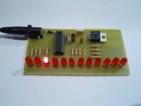
This simple circuit functions as a 12 LED chaser. A single illuminated LED ‘walks’ left and right in a repeating sequence, similar to the effect seen on KITT, the car in the Knight Rider TV series.
Fully commented source code and programmer ready HEX files are provided for the PIC 16F84A and 16F628A at the bottom of this page.
The circuit has been constructed on a PCB but can easily be built on strip-board, or a solderless breadboard.
This project has been put together for anyone starting with their first PIC and the source code is heavily commented with references to the PIC datasheets and the MPASM assembler user guide.
Although the PIC 16F84A is really obsolete and I wouldn’t normally do a project using it, this chip is used extensively throughout education and for many people this will still be their first step into the world of PICs. I’ve also written a version for the PIC16F628A which is a pin compatible replacement for the 16F84A and I would recommend that if you intend to develop your interest in PIC microcontrollers you start using this device rather than the 16F84A.
Please note that the 16F84 and 16F628 without the ‘A’ suffixare not suitable for this project. You must use the 16F84A or 16F628A parts.
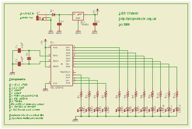
The heart of the LED chaser is the PIC microcontroller, IC1. This can be either a PIC16F84A or PIC16F628A as software code is provided for either device. The program that runs on this chip controls the LEDs attached to the output port pins. Resistors R1 thru R12 limit the current through LED1 – LED12 to a safe level that won’t damage the PICs I/O ports or LEDs.
The value of the resistors has been selected to be safe rather provide maximum brightness. If you decide to use high brightness blue, green or white 5mm LEDs you may need to change these from 270ohms to 100ohms. For all other 5mm LEDs the 270ohm resistors will be fine.
Crystal Q1 and capacitors C1 and C2 connect to the oscillator circuit inside the PIC. This generate a stable 4Mhz clock which is used by the PIC to control the timing of the microcontroller core. If you are using the PIC 16F628A you can omit these three components and use the PICs internal RC oscillator. However, you will also need to make a change to the source code before programming the PIC so it knows to use it’s internal oscillator. (see here)
Capacitor C3 is used to decouple the 5 volt power supply rail. If you are building the circuit on a breadboard or stripboard you should ensure it is located close to the PICs Vdd connection (pin 14 ).
The input voltage can be anywhere form 9 to 12 volts but the PIC requires a precisely controlled 5 volt supply. This is provided by IC2, a 78M05 3-terminal 5 volt regulator. Capacitor C4 decouples the input to the regulator. Diode D1 protects the circuit from accidental reverse polarity of the input voltage.
You can buy all the parts needed to build this project from most component suppliers world wide. In the UK you can get everything from Rapid Online and I’ve included a parts list with their part numbers below.
All Rapid parts/descriptions correct at 04-Sept-2008. You should check part# and descriptions are correct when ordering in case I’ve made a mistake transferring them onto this page.
* You can use almost any type of 5mm standard LEDs of any colour with this circuit. If you use blue LEDs you may need to change R1-12 from 270R to 100R.
** use either PIC16F628A or PIC 16F84A
*** If you don’t have a power supply, this one should be suitable.
PIC Programmer
You can also buy the PICkit2 starter kit from Rapid, part # 97-0101
Construction notes:
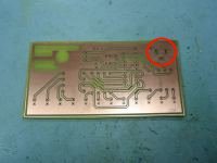
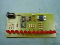
In Fig 1. note how the holes for the DC Power Jack (top right) have been milled into slots to accept the solder tabs on the connector.
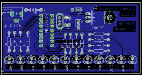
The photo shows PCB410A, the artwork and Eagle files on this page are for PCB410B. I’ve made some minor changes to the copper layout to make it easier to solder the LEDs but the component placement remains unchanged.
Fig. 2 shows the board with the 4Mhz crystal and capacitors fitted. This board will work with the firmware on this page without modification.
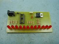
In Fig.3 crystal Q1, and capacitors C1, C2 have been omitted. If you are using a PIC 16F628A you can use the PIC’s internal RC oscillator, in which case you don’t need to fit these components. If you do this you will need to edit the ‘ledchaser16F628A.asm’ file.
You will then need to reassemble the file. If you have installed the Microchip MPLAB IDE software, you can load the asm file and then do a Project – Quickbuild to create the HEX file. Once you’ve done this, program the 16F628A with the new ledchaser16F628A.HEX file.
Fig. 4 shows the board running the LED Chaser program.
Power Supply
The board includes a 5 volt regulator and reverse polarity protection diode on board. You will need to use a suitable DC power supply rated between 9 and 12 volts and able to supply at least 200mA.
In the UK you can buy a suitable power supply from Rapid Electronics. The part number for this is included in the component listing above should you not already have something available.
Firmware
You can use either a PIC 16F84A or PIC 16F628A microcontroller with this circuit. Download the files required below.
The HEX files are ready to program straight into the PIC. The asm files are the source code which you can modify or just view to see how it works. If you are going to modify the code I recommend you download and install the Microchip MPLAB IDE which will allow you to edit, modify and program the PIC seamlessly.
If you need a PIC Programmer I strongly recommend the Microchip PICKit 2, this is available from suppliers world wide or direct from Microchip. It’s reasonably cheap to buy and reliable. I have a couple of them and I wouldn’t use anything else now.
As noted elsewhere, the code above will not work with the non ‘A’ suffix parts. While the changes to make it work are minor, I haven’t tested them and therefore I will only support it when used with the 16F84A / 16F628A. Also be aware that the PICkit2 programmer does not support the 16F84 but it does support the 16F84A.
Quick Solutions to Questions related to 12 LED Chaser:
Can I use a non-A suffix PIC chip like the 16F84? No, you must use the 16F84A or 16F628A parts as the code is not tested for non-A versions.
How do I change the resistor values for blue LEDs? If using high brightness blue, green, or white 5mm LEDs, change resistors R1-R12 from 270ohms to 100ohms.
What happens if I omit the crystal and capacitors? You can omit them if using a PIC16F628A with its internal RC oscillator, but you must edit the source code configuration.
Does the circuit require an external power supply? Yes, the board requires a DC power supply rated between 9 and 12 volts capable of supplying at least 200mA.
Can I build this project on a breadboard? Yes, the circuit can be constructed on a PCB, strip-board, or a solderless breadboard.
Which programmer is recommended for this project? The Microchip PICkit 2 is strongly recommended as it is reliable and supports the required chips.
Where can I find the source code for modification? Source code in ASM format and ready-to-program HEX files are provided for both PIC16F84A and PIC16F628A.
What is the function of capacitor C3? Capacitor C3 is used to decouple the 5 volt power supply rail and should be located close to the PICs Vdd connection.
Can I use different colored LEDs than red? Yes, almost any type of 5mm standard LED of any color can be used with this circuit.
Do I need to install MPLAB IDE to use the provided files? It is recommended to install Microchip MPLAB IDE if you plan to modify the source code, though HEX files work without it.
I am an experienced technical writer holding a Master's degree in computer science from BZU Multan, Pakistan University. With a background spanning various industries, particularly in home automation and engineering, I have honed my skills in crafting clear and concise content. Proficient in leveraging infographics and diagrams, I strive to simplify complex concepts for readers. My strength lies in thorough research and presenting information in a structured and logical format.
This website uses cookies to improve your experience. We'll assume you're ok with this, but you can opt-out if you wish. ACCEPTCheck Privacy Policy
Manage consent
Privacy Overview
This website uses cookies to improve your experience while you navigate through the website. Out of these, the cookies that are categorized as necessary are stored on your browser as they are essential for the working of basic functionalities of the website. We also use third-party cookies that help us analyze and understand how you use this website. These cookies will be stored in your browser only with your consent. You also have the option to opt-out of these cookies. But opting out of some of these cookies may affect your browsing experience.
Necessary cookies are absolutely essential for the website to function properly. This category only includes cookies that ensures basic functionalities and security features of the website. These cookies do not store any personal information.
Any cookies that may not be particularly necessary for the website to function and is used specifically to collect user personal data via analytics, ads, other embedded contents are termed as non-necessary cookies. It is mandatory to procure user consent prior to running these cookies on your website.
download