Introduction
Fighting games are rising in popularity around the globe. However, a consistent barrier to new player entry has been the difficulty of the inputs. Rather than pressing a single button for attacks and moves, fighting games often require complex frame-perfect combinations of buttons to perform combos necessary to compete at even basic levels. Many new players find that learning these combos and button strings are not worth learning, and become disenchanted with fighting games early on. This problem also extends to players at the highest level, who may have difficulty consistently inputting the most powerful and optimal combos possible.
To help solve this problem, we created a project called TKButtons. With the modified controller (Betsy) and our program, you can record your combo ahead of time, and then playback during the game. The controller contains a PIC32 microcontroller and some circuity which allows the player to play the game through a arcade stick. When the player is ready, then the player can hit the record button. The PIC32 controller then keep tracks when each button and stick input were hit and the time that they were hit. To finish the recording, the player hits one of the playback buttons. To play the recording, the player just needs to hit either the left or right playback button. The PIC32 will then play through the button/stick inputs that were just recorded. The player can also cancel the recording and the playback whenever they want. In this project, we will be mostly explaining the controller in use with the game Guilty Gear. If you are unfamiliar with the game, we recommend you to check out the appendix which have guides and instruction to all the different moves that we are explaining on this website.
Take Tiger Knee Bomber (TKB) for example, the case study for this project. In the game Guilty Gear, the player controls Axl Low to do this combo. To do massive damage however, the player needs to loop TKB three times and then break the wall. This combo can do up to 60% of the opponent HP. However, the combo loop is know to be hard to pull off, which can lead to player when they mess up to be vulnerable to the opponent attack. With this project though, the player can easily record the TKB combo beforehand, and then just hit the playback button at the right timing.
The video below shows the full project including the TKB Combo. Thanks to Professor Hunter for being the guinea pig for our demo.
High Level Design
With the release of the fighting game “Guilty Gear Strive”, traditional 2D fighting games are increasing in popularity. The main reason why fighting games are very daunting and difficult to get the hang of easily is because they require very precise inputs, often requiring inputting a series of buttons almost perfectly timed, within a few frames of each other, though this may vary between different fighting games. Guilty Gear Strive is known for being more newbie-friendly than the average fighting game, but still requires the player to be able to do very precise inputs when playing at a high level. To attempt to alleviate the player of this issue, we decided to create a way for players to record their favorite combos onto an arcade stick to ensure they would not have trouble executing the combo whenever they wanted.
Logical Structure
From the software perspective, we split the funtionality of our project into three main threads: One for reading inputs, one for recording, and one for playing them back. This paid off, as it allowed us to quickly narrow down bugs in our design to specific threads in our code. Our circuit directly connects to the inputs of the arcade stick as well as to the port expanders, which is driven by the PIC32 on the ECE4760 small board. This is why writing to the port expander ends up “pressing” buttons on the arcade stick. Our connections ensure that the PIC32 drives the arcade stick.
Hardware/Software Tradeoffs
We made some design choices for the hardware portion of our project that motivated our design for the software. Originally, we planned to work on this project with a classic XBOX 360 controller. After a lot of research, we concluded that using an arcade stick would be the better choice, as they are easily modifiable by the user. Making this design choice likely saved us weeks, maybe even an extra month of development time. Additionally, we decided to use multiple port expanders instead of a shift register, as although it might have made our circuit potentially easier to build, manage, and debug, it would also demand that we find or make an entirey new library for the shift register. Using a second port expander made our circuit significantly more complex, but eliminated the need to familiarize ourselves with a new interface.
Program/Hardware Design
Hardware Design
The hardware of our final project is designed to enable the PIC32 to read the button inputs, spoof the button so that the button appears pressed to the PCB onboard the arcade stick, and so that all circuits leading back to the PIC32 are electrically protected. Our project is responsible for controlling 12 buttons related to gameplay, as well as reading three buttons to control recording and playback. To illustrate how all 12 of the button control circuits work, we will examine the data path of one of them.
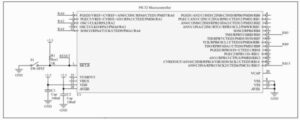
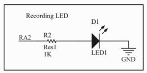
The signals interfacing with the buttons originate from the PIC32 over a single SPI channel. The software onboard uses SPI to communicate with two port expanders which we use to communicate with all buttons on board. RB15 is SCK, RB5 is MOSI, and RA4 is MISO. The chip selects are RB9 for port expander 1 and RA0 for port expander 2. The final connected pinout is RA2, which is used to control the recording LED. The recording LED illuminates when the software is recording inputs. No other headers on the PIC32 are connected other than the necessary power, ground, and reset button.
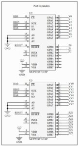
The SPI channel is responsible for interfacing with two port expanders. Each button on the arcade stick receives two GPIO pins: one for reading the button state (input), and one for controlling if the button is electrically pressed or not (output). Since we have 12 buttons, we need 24 GPIO pins in addition to the three record/playback control buttons, bringing the total to 27 GPIO pins. The PIC32 is unable to accommodate so many GPIO pins, so external port expanders are required. Each port expander has 2 ports of 8 pins, so we decided to use two port expanders to have 32 available pins to use, of which we use 27. The reset of the port expander is tied together with that of the PIC32, and the configuration pins are all grounded as they are on the big board from class. The interrupt pins are not connected since the software uses polling to check the buttons. Each pair of GPIO pins, for example Y0 and Y1, are responsible for controlling a single button. Even numbers (0, 2, 4, 6) are inputs, and odd numbers (1, 3, 5, 7) are outputs. Using this GPIO scheme we were able to mitigate confusion during the wiring process.
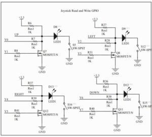
Figure 4 shows the circuitry for the joystick’s GPIO. This circuit is duplicated twice: once for the XYAB GPIO, and one for the LT LB RT RB GPIO. Thus, we have 12 button control circuits total. Each button is represented by an SPST switch. When the button is pressed, both the GPIO input from the port expander and the input from the PCB read low. Otherwise, the circuit is connected to a 3.3V pullup so they read high. This matches the hardware on the arcade stick. When the button is pressed, an indicator LED also lights up to confirm that the button is registered as pressed. The second GPIO from the port expander is an output and is connected to the gate of an n-channel MOSFET. When the output is set high, the MOSFET allows current to flow through and forces the node at the drain to be electrically low. This can be read on the port expander and PCB. In addition, this turns the LED on as well. As a result the LED in each circuit is extremely useful for debugging.
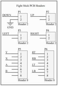
On the arcade stick, each button has two inputs, one of which is pulled up. The ground of one of these inputs is connected to the PIC32 ground so that the PCB logic highs and lows can be manipulated by the PIC32. The rest are not connected for simplicity. The arcade stick inputs are connected to the corresponding node of the GPIO inputs from the port expander.
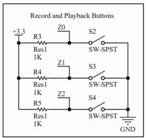
The record and playback control buttons are onboard the arcade stick on a separate PCB. The wires from the PCB header we are concerned with are the three logic wires pulled high responsible for reading each button, and a single ground wire. The logic wires are spliced so that they can be plugged into the port expanders for reading.
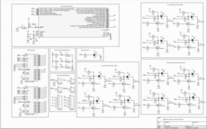
When all components work in tandem, the software is not only able to control the outputs of each button and read the state of each button, but also able to receive input from the user to determine whether a combo should be recorded or played back.
Software Design
The software is designed to record a single combo and the timing of the inputs, as well as play the combos back with said timing. The program is split into four parts: the setup, the read button thread, the record/playback control thread, and the write button thread. The setup occurs at the top of the program file and inside the main file.
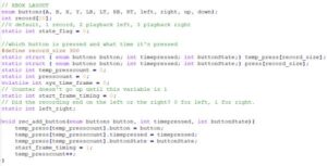
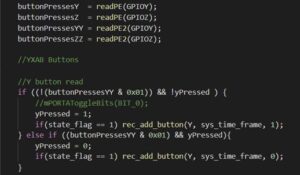
The protothread_key thread focuses on reading the button presses and adding it to the temp_press. We have define multiple variables which will track the state of each button on the arcade stick (X,Y,A,B, etc). Additionally, we defined the buttonPressesY, buttonPressesYY, buttonPressesZ, buttonPressesZZ variables, which will store the value returned after reading the first and second port expanders. The thread will check if the pin corresponding to the button is set (checking if the correct bit is set to zero) and if the specific button has not been pressed. If this condition is true, then the input is added to the temp_press array. If the exact opposite condition is true, the input will still be added, but with the buttonState argument set as a 0. This indicates that the button was released (negative edge) instead of pressed (positive edge).
The protothread_record thread defines behavior of the record and playback buttons. We first need to read port Z of the port expander as those are connected to the record, playback left and playback right buttons. Next, we check if the record button has been pressed with a very similar approach to the one used in figure 8, except this time, an LED will light up to indicate that we are recording, whereas pressing the record button again will turn off the LED. If we are currently in record mode and we press the left playback button, our code will record all the buttons inputted between those two events and will set a flag which indicated if the left playback button has been pressed. This will clear the record flag. Next, if we are not in record mode and we press the left playback button again, we will go into playback mode, where we playback all the inputs recorded, and directional inputs are reversed depending on whether the player is on the left or right side of the screen. This logic is repeated for the right playback button as well.
Finally, the protothread_playback thread will playback the inputs stored in the temp_press array. We first check if we are in playback left or playback right mode, then we check if the system time is zero. If this is true, we save the previous set of inputs and outputs to and from the port expander. If we also observe that the previous input is not the same as the current input, we write all zeros to the port expanders. This is to cancel any recording in progress. Afterwads, we check the array of inputs to be played back, and make use of a switch case statement to write specific numbers corresponding to the pressed button to the port expander. This will “press” a button on the arcade stick, thus playing back all buttons pressed.
Results
Throughout the course of this final project, we documented every major stage in our development process and submitted weekly progress reports. The first week working on our project mainly involved doing a lot of research on how we could feasibly modify the arcade stick. This week involved a lot of planning and roadmap setting so we were sure we could complete the project by the deadline. After considering the pros and cons of using a shift register to make multiple IO pins for recording and playing back our circuit as compared to just using a port expander, we finally agreed on using a Port Expander to make more pins to use for reading and writing our buttons. This is because of multiple factors. Firstly, we would have to write an entirely new library, or learn how to use an existing library for the shift register, which could take a week or longer. The port expander code we used in the course is already proven to work, and we can edit the library as needed to support multiple port expanders, which is what we ended up doing for the lab. Before doing this, we also confirmed that the joystick directional inputs were digital so we wouldn’t need to use an ADC for our project.
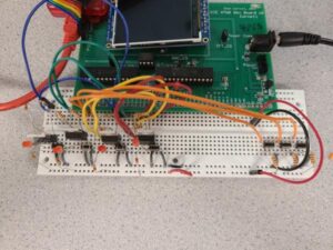
The following two weeks were spent working on basic code for recording button presses for our circuit, as well as working on a small circuit (See Figure 1) to test recording and playing back inputs. We came across many hardware and software bugs, the most notable of them being the record and playback code not working properly. This came in the form of the LEDs staying lit up sometimes, or the series of button presses just not playing back. After careful debugging and checking our connections to the port expander, we were finally able to resolve the issue.
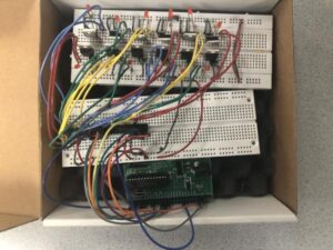
The next major milestone was to build the final circuit (Fig 2). This was likely the most debugging-intensive part of the final project. After building the final circuit, we would observe a lot of strange behavior of the LEDs. This was a combination of the LEDs staying on when they weren’t supposed to, LEDs dimming, and LEDs not responding as expected when the button was being pressed. After some discussion with the course instructor, we decided to replicate the circuit on a protoboard. This also did nothing to solve the issue. After careful deliberation, we decided to review the schematic, and discovered that there were some disconnected pins to the port expander. After connecting these, and some light debugging of the record and playback code, as well as writing an entirely new library for the second port expander, we were finally able to read from and write to the port expanders, and tested this with simple code that would blink all the LEDs in our circuit.
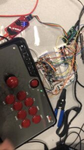
Now that we were finished with most of the code, it was time to wire everything to the arcade stick. This was a relatively simple endeavor, and once we had connected them all, we tried to record and playback input and visualize it using the fighting game. We noticed that it would record and playback correctly, but we would playback the wrong buttons. This required a simple, but somewhat tedious fix, as we would need to make sure all the connections to the buttons were correct and most importantly, consistent with our code. The final product is as shown below (All wires go under the Arcade Stick!). The following video showcases the TKB input described in the introduction being played back three times in quick succession. The inputs are played back with astounding accuracy, shown in the animation in the bottom left corner of the game.
Conclusion
We are pretty pleased with this project. We completed the project with a bit of time to spare though that’s not without annoying debugging of both the hardware and software variety. We still have some bugs that we didn’t have time to get through such as the fast RC (roman cancel) combos not between inputted correctly. Fast RC are explained in the appendix. We think that the PIC32 controller doesn’t record it fast enough and therefore it doesn’t record the RC in time. However, we didn’t have enough time to figure it out.
This device actually conform to the applicable standard which the controller can be used in gameplay. Since all the hardware and software are within the controller, then a person can cheat with the controller as an anti-anti cheat device. Most anti-cheat software tries to detect if the player are using some sort of software to like increase their health or to give unlimited bar. However, the controller only allows the player to cheat only with recording combos beforehand and then playback during the match. Another thing to improve our design is related to these anti-cheat software. We can imagined that there’s some anti-cheat software that will detect if the player uses the combo with the same timing as before and will flag the player. To beat that anti-cheat software in particular, we can probably vary the timing of the combo from the PIC32. Then the anti-anti-cheat hardware will be actually undetectable. I would not recommend though bringing this controller to a in-person tournament since people can see your buttons though. However, play away with this controller in a online tournament!
In addition to an anti-anti-cheat device for all types of players, it can also be used as an accessibility device as long they have another person to actual input the combo at first. Some people might not be able to do certain combos due to disabilities. Our controller, as long someone else input the combo, will let the person play the combo with only a tap of a button, letting them use the hardest combos with ease.
Intellectual Property Considerations
We did reuse some of the code used in this class, however, most of the software was designed on our own. We did have to reverse engineered a bit of the controller to understand how the controller get the inputs from the buttons and the joystick. We opened the inside to see it as seen in Figure 1 below. We didn’t get permission techincally from the company to open up the controller. However, the controller manufacturers know that the fighting community does mod their joystick controller, and therefore it’s expected that the joystick controller will be opened at some point. As such, We don’t expect it to become too much of a problem not getting permission.
Ethical Considerations
Though our design does promote cheating which is unethical in it’s own sense, it doesn’t hurt or exclude anyone which the IEEE Code of Ethics deals with.
Safety Considerations
There’s none that we can really think of unless the user is stupid.
Legal Considerations
The only additional hardware/software that we used is the controller which was explained in the Intellectual Property Considerations.
