Summary of DC MOTOR INTERFACING WITH 8051 MICROCONTROLLER
This article explains interfacing a DC motor with an AT89C51 8051 microcontroller using L293D and L298N motor drivers. It details why direct connection is unsafe due to current limits and back EMF, highlighting that these drivers control motor direction and speed via H-bridge logic. The text provides specific voltage and current ratings for both ICs, lists required components, describes the circuit design connecting pins to switches, and outlines the algorithm for controlling rotation based on button inputs.
Parts used in the Interfacing DC Motor with 8051 Microcontroller:
- AT89C51 (8051 Microcontroller)
- 8051 Programmer
- Programming cable
- 12V DC battery or Adaptor
- L293D motor driver
- DC motor
- Electrolytic capacitor – 10uF
- 2 Ceramic capacitors – 33pF
- 10k resistors (1/4 watt) – 4
- Push Buttons – 3
- Connecting wires
In this project, we will learn about L293D and L298N Motor Drivers and also about Interfacing DC Motor with 8051 Microcontroller with the help of both L293D and L298N.
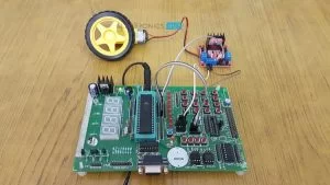
When we talk about controlling the robot, the first thing comes into the mind is controlling DC motors. Interfacing DC motor to the microcontroller is very important concept in Robotic applications. By interfacing DC motor to the microcontroller, we can do many things like controlling the direction of the motor, controlling the speed of the motor. This article describes you how to control the DC motor using AT89C51 controller (or any variant of 8051 Microcontroller).
Circuit Principle
The maximum output current of microcontroller pin is 15mA at 5V. But the power requirements of most of DC motors is out of reach of the microcontroller and even the back emf (electro motive force) which is produced by the motor may damage the microcontroller.
Hence, it is not good to interface DC motor directly to the controller. So, we use motor driver circuit in between a DC motor and the microcontroller.
Also read the interesting concept: Interfacing 7 Segment Display to 8051 Microcontroller
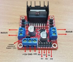
Here, we are using L293D and L298N motor driver ICs to drive DC motors. Using these IC’s, we can drive two DC motors at a time. For L293D Motor Driver, the motor supply is variable between 4.5 to 36V and it provides maximum current of 600mA. In case of L298N, the motor supply is up to 46V and it can provide a current of 3A.
A Brief Note on L293D Motor Driver
L293D is a quadruple H- bridge motor driver, as the name suggests it used to drive the DC motors. This IC works based on the concept of H- Bridge. H-bridge is a circuit which allows the voltage in either direction to control the motor direction.

There are 4 input pins for L293D. Motors directions depends on the logic inputs applied at this pins. EN1 and EN2 must be high to drive the 2 DC motors.
- IN1=0 and IN2=0 -> Motor1 idle
- IN1=0 and IN2=1 -> Motor1 Anti-clock wise direction
- IN1=1 and IN2=0 -> Motor1 Clock wise direction
- IN1=1 and IN2=1 -> Motor1 idle
- IN3=0 and IN4=0 -> Motor2 idle
- IN3=0 and IN4=1 -> Motor2 Anti-clock wise direction
- IN3=1 and IN4=0 -> Motor2 Clock wise direction
- IN3=1 and IN4=1 -> Motor2 idle
A Brief Note on L298N Motor Driver
The L298N Motor Driver Module is more frequently used driver IC’s now-a-days. The current and voltage ratings of L298N are higher than that of L293D Motor Driver.
For more information on L298N Motor Driver Module, refer to the “A BRIEF NOTE ON L298N MOTOR DRIVER“.
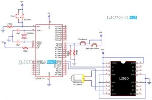
Circuit Diagram for Interfacing DC Motor with 8051 Microcontroller and L293D
Components Required
- AT89C51 (8051 Microcontroller)
- 8051 Programmer
- programming cable
- 12V DC battery or Adaptor
- L293D motor driver
- DC motor
- Electrolytic capacitor – 10uF
- 2 Ceramic capacitors – 33pF
- 10k resistors (1/4 watt) – 4
- Push Buttons – 3
- Connecting wires.
Get an idea about How PWM Based DC Motor Speed Controlling Circuit Works using Microcontroller
Circuit Design
The major components in the above circuit diagram are at89c51 microcontroller and motor driver. Here, the motor driver input pins IN1, IN2 are connected to the P3.0 and P3.1 respectively to control the motor directions. DC motor is connected to output terminals of L293D. EN1 pin is connected to the 5V DC to drive the motor.
Switches are connected to the P2.0 and P2.1 of the Microcontroller in pull down configuration. First switch rotates the motor in clockwise direction and second switch rotates the motor in anti clockwise direction. 8th and 16th pins of the motor driver are connected to the +5V supply.
Do you know How to Control Stepper Motor using 8051 Microcontroller?
Algorithm
- Declare P2.0 and P2.1 as inputs and P3.0 and P3.1 as outputs.
- Now check weather the first button is pressed or not. If pressed, then send logic one to P3.0.
- Next check whether the second button is pressed or not. If pressed, then send logic 1 to P3.1 otherwise send 0 to port 3.
Source: DC MOTOR INTERFACING WITH 8051 MICROCONTROLLER
- Why should a DC motor not be interfaced directly to the microcontroller?
Direct interfacing is unsafe because the microcontroller pin output current is only 15mA at 5V, which is insufficient for most motors, and the back EMF produced by the motor may damage the controller. - What are the voltage and current ratings of the L293D motor driver?
The L293D supports a variable motor supply between 4.5 to 36V and provides a maximum current of 600mA. - How does the L298N compare to the L293D in terms of power handling?
The L298N has higher ratings than the L293D, supporting a motor supply up to 46V and providing a current of 3A. - Which pins of the AT89C51 are used to control the motor directions?
The motor driver input pins IN1 and IN2 are connected to P3.0 and P3.1 respectively to control the motor directions. - How are the switches connected to the microcontroller in this project?
Switches are connected to P2.0 and P2.1 of the microcontroller in a pull-down configuration. - What logic levels cause the first motor to rotate in the anti-clockwise direction?
Setting IN1=0 and IN2=1 causes the first motor to rotate in the anti-clockwise direction. - What is the function of the EN1 pin on the L293D driver?
The EN1 pin must be connected to 5V DC to drive the two DC motors. - How many DC motors can be driven simultaneously using the L293D IC?
Using the L293D IC, you can drive two DC motors at a time.