Summary of DC motor control with PIC16F84A and L293D
Summary: This project controls a 12V DC motor’s speed and direction using a PIC16F84A microcontroller and an L293D half H-bridge driver. Five buttons adjust speed, direction, and stop; three LEDs indicate direction and maximum speed. Software PWM at 500 Hz (via CCS C PWM library using Timer0) varies duty cycle to change motor speed. L293D V S = motor supply (12V) and V SS = +5V.
Parts used in the DC motor control with PIC16F84A and L293D:
- PIC16F84A microcontroller
- L293D motor driver IC (half H-bridge)
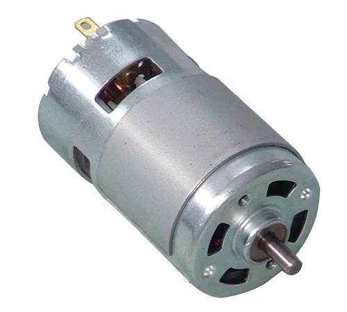
- 12V DC motor (nominal 12V)
- Five push-button switches (speed up, speed down, direction1, direction2, stop)
- Three LEDs (LED1 direction, LED2 direction, LED3 maximum speed)
- Resistors for LEDs and button pull-ups/pull-downs as required
- 5V regulator or 5V supply for VSS
- 12V supply for motor and L293D VS
- Breadboard or PCB and interconnect wiring
Low power DC motors can be easily controlled with half H-bridge IC L293D. This IC is 16-pin IC which can control 2 motors in both directions.
This topic shows how to control DC motor speed and direction with PIC16F84A and L293D motor drive integrated circuit.
Related topics:
The following topic shows how to control a DC motor with PIC16F84A and H-bridge circuit.
DC Motor speed and direction control with PIC16F84A using H-bridge
DC motor control with PIC16F84A and L293D circuit:
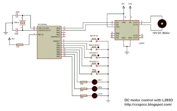
Project circuit schematic is shown below
The nominal voltage of the motor is 12V as well as L293D VS input voltage. Always L293D VS voltage is the same as the DC motor voltage and L293D VSS voltage is +5V.
In the circuit there are 5 buttons, the first button which is connected to RB0 pin is used to speed up the motor, and speed down button to decrease motor speed. Third and fourth buttons are used to choose direction rotation of the motor (direction 1 or direction 2). The last button stops the motor no matter what speed or direction.
There are 3 LEDs, LED1 and LED2 are used to indicate motor direction, and the other LED indicates maximum speed, which means when it is on the motor is running at maximum speed.
When speed up button is pressed the PWM duty cycle increases which causes the motor to increase its speed and when the duty cycle = 100 LED 3 turned on. In the other hand if speed down button is pressed the duty cycle decreases and the motor speed also decreases.
If the stop button pressed the motor stops and the 3 LEDs are off.
Software PWM is used wih frequency of 500Hz.
DC Motor control with PIC16F84A and L293D CCS C code:
The full C code is shown below. Official software PWM library which comes with CCS PIC C compiler is used, this library uses Timer0 to generate the PWM signal.
Read more: DC motor control with PIC16F84A and L293D
- What motor supply voltage should be used?
The nominal motor voltage is 12V and L293D VS should be the same as the motor voltage. - What voltage is applied to L293D VSS?
L293D VSS voltage is +5V. - How many buttons are used and what do they do?
Five buttons are used: speed up, speed down, direction 1, direction 2, and stop. - How many LEDs are used and what do they indicate?
Three LEDs: two indicate motor direction and one indicates maximum speed when on. - How is motor speed controlled?
Motor speed is controlled by changing the PWM duty cycle; increasing duty cycle increases speed. - What PWM frequency is used?
Software PWM is used with a frequency of 500 Hz. - Which timer does the software PWM use in this project?
The official CCS C software PWM library uses Timer0 to generate the PWM signal. - What happens when the stop button is pressed?
If the stop button is pressed the motor stops and all three LEDs are off. - When does the maximum speed LED turn on?
The maximum speed LED turns on when the PWM duty cycle reaches 100%.