Summary of Autonomous Drone
This project integrates autonomous flight capabilities into a custom drone by using a PIC32 microcontroller to manage high-level control signals (throttle, pitch, roll, yaw) for an existing KISS flight controller. The system utilizes GPS for location tracking, a magnetometer for heading, and Wi-Fi for remote communication with a smartphone app. Key challenges included hardware assembly, configuring UART and I2C communications, and establishing a PWM-based killswitch for safety.
Parts used in the Autonomous Drone:
- OnShape CAD tool
- Laser-cut 5mm wood frame
- RCX H1105 brushless motors
- 4-in-1 ESC
- KISS flight controller
- Betaflight configurator software
- Adafruit Ultimate GPS Breakout Version 3
- Triple-axis Accelerometer+Magnetometer Board (LSM303DLHC)
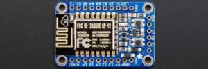
- Adafruit HUZZAH ESP8266 Breakout
- PIC32 microcontroller
- Flysky transmitter and receiver
- Pololu 5V 1A Voltage Regulator D24V10F5
- Android Studio app
Introduction
The main goal of my project was to add autonomous flight capabilities to a simple drone framework. I have seen many projects in the past which attempt to develop a flight controller for a drone. While the theory behind this is rather simple, it can be hard to acheive great results in practice. Rather than dealing with the PID tuning of flight control, I have chosen to use an existing flight controller to control the drone, while feeding it inputs with the PIC32. In this way, I do not have to worry about stability, but rather can focus on the high level throttle, pitch, roll, and yaw channels.
The original vision was to construct a drone which will follow the user (really a phone) according to GPS data and magnetic heading information. This of course required a base drone framework to run off of. The project could largely be separated into three sections.
- Drone Construction
- This section consisted of designing and building a funcioning drone. At this stage, no autonomy was added. Instead, the drone could be flown and tested using a typical receiver and transmitter.
- Peripheral Device Communication / Data Acquisition
- This section consisted of communicating with the required sensors to receive the necessary data for autonomous flight. In this case, the sensors consisted of a GPS module, magnetometer, and wifi module.
- PIC32 Control of Drone
- This section consisted of establishing a connection between the PIC32 and flight controller to allow it to fly and operate on its own.
A number of peripherals within the PIC32 were utilized in this project. In particular:
- Interrupts
- Timers
- IO Ports
- Output Compare
- UART
- I2C
This project was rather ambitious and had many sections which all had to come together, however, it deals with an increasing aspect of today’s world; autonomy within robotics. Even more specifically, all sorts of drones (autonomous, hobby, military) have becomre more and more prevelant.
Drone Framework
Overview
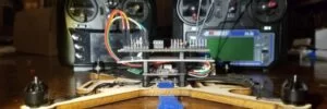
Rather than focusing on the development of a precise flight controller to control the movement of a drone, I chose to extend the functionality of an existing drone. In order to do this, however, I had to have a functioning drone which allows me tap into all of the required signals. I began by looking at the possiblity of just purchasing a solution to the problem. Drones have become more prolific than ever, and it is quite easy to find a decent drone for under $50. The issue is that most of these drones are fully contained. There is very little room for modification if any. Because of this, it became apparent that I would have to build my own drone from various parts. While this provided me with the most flexibility over design, a large part of the project was spent building the actual drone. The rest of this section outlines the various parts of my drone build.
Framework
My drone began as some simple sketches in the online CAD tool, OnShape. In designing the frame, I tried to make it as functional as possible for my project. I knew that I would have numerous sensors which had to be placed on the drone in addition to the flight controller. In order to accomodate this, I added mounting holes and cutouts for the main boards. In the center of the drone are two sets of four holes. The inner set is used to mount the ESC, while the outer set are for the flight controller. The flight controller is lifted off of the framework, and sits above the ESC to improve space management. At the front of the drone sits the GPS module. On the other side are the magnetometer as well as the wifi unit at the very end. I also made the frame large enough to eventually support propellers which are up to five inches. Once I had completed the design, I laser cut the frame out of 5mm wood. While this is not the most suitable material for the job, it was easy and allowed for cheap and rapid prototyping. Below are images showing the design of my framework. My design is available for download as a DFI: drone framework
ESC’s and Motors
Once I had the framework complete, I could begin assembling the various parts required for the most basic drone to fly. This began with the motors and ESC’s. The motors I used were RCX H1105 brushless motors. These motors have a KV value of 4000 and are decently small, but are sufficient for my purposes. Each of these motors must be controlled by an ESC (Electronic Speed Control). This unit provides power to the respective motor when a signal is sent from the flight controller. Often times you will have a standalone ESC for each motor, however, I used a 4-in-1 ESC which helped to simplify the design. All four motors connected to a single board which was mounted in the center of my framework. On the left of the ESC board, are all of the required connections. First, I routed power to the board using wires coming from the battery connector. This can be a little difficult to see in the image as the solder pads are on the bottom of the board. On the top is a six pin port for the signals. The minus connection is ground comming from the flight controller, and 1, 2, 3, 4 are the four motor signals. The positive connection on this board does not serve any purporse. The flight controller I used for this project has a similar port to this one, so I was able to decrease the required soldering by using the provided ports.

Flight Controller
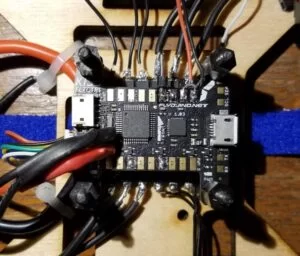
After some research, I chose to use the KISS flight controller for this project. The KISS is a relatively inexpensive flight controller which provides more than enough functionality for what I need. I mounted the KISS similar to the ESC, but utilized standoffs to raise it up slightly off of the framework. I was able to jump the same power to the flight controller since it has its own power regulator and is able to take 2S to 6S battery packs. In addition to the power, I connected the signal wires going to the ESC into the port. The ordering of the signals was slightly different, so I had to make sure the wires were in the correct order. On the KISS, the 6th connection on the port is meant to be telemetry coming from the ESC. Since there is no connection on the ESC, I will not be able to get telemetry data back (I didn’t want it anyway). Once this was set up, I could configure and test the drone thus far. First, I had to flash the KISS with the most current firmware. This along with all of the configuration was done with the Betaflight configurator. Once the flight controller is connected, you can adjust settings for your specific build as well as test various aspects of the system. For example, I tested the mapping of the motors to ensure they were in the correct order. Once the necessary configuration was complete, I plugged a simple standalone PPM receiver into one of the flight controller’s ports, and could fly the drone using a transmitter.
GPS
Overview
In order to make decisions on movement direction, the drone must have some way of knowing where it is. The most common solution to this is a global positioning system (GPS). From this, the drone can figure out its latitude, longitude, altitude, and even velocity vectors. GPS systems are quite complex themselves, and a lot of development has already gone into them. So much so that you can easily purchase a standalone unit which will provide you with the requested data.
Hardware Setup
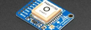
For this project, I chose to use the Adafruit Ultimate GPS Breakout Version 3. This is a breakout board provided by Adafruit, which is built around the FGPMMOPA6H (MTK3339) standalone GPS module. The breakout board provides some very nice extra functionality including:
- A 3.3V regulator is included allowing you to power the device with 3.3-5V
- ENABLE pin allowing you to turn off the device using a microcontroller pin
- A footprint for optional CR1220 coin cell to allow for warm starts
- A red LED for FIX data
- Ability to add an external antenna
For my purposes, I did not require many of these extra features, but Adafruit breakout boards are always great to have. As far as the actual GPS module goes, the communication protocal is universal asynchronous receiver/transmitter (UART). After receiving power, the board will begin transmitting with a frequency of approximately 1Hz. Each message is a sequence of ascii characters terminated by a CRLF. Prior to acheiving a FIX, the transmitted data will have no meaning. In messages containing GPS data, the actual values will often be omitted. For further details on the messages see the section on NMEA sentences. Various options regarding the module can be set by transmitting specified sentences to the GPS. For example, the update rate can be changed as well as requesting data on satellites.
NMEA Sentences
NMEA is a specification that defines the interface between various pieces of marine electronic equipment; this includes GPS systems. MTK products have defined a set of NMEA output sentences. The main one I am interested in for this project is RMC. This sentence includes time, date, position, course and speed data and is the minimum recommended navigational information. Once I receive an output sentence from the GPS unit, I need to parse out the required data. Thankfully, Adafruit has developed an C++ library for use with the module. In particular, they have written a NMEA sentence parser which extracts all available data. Although this code is in C++, I was able to transfer most of it into C for use on the PIC32. The core difference was the UART communication between the PIC32 and the GPS module. The Adafruit code can be found here: Adafruit_GPS.
UART Communication
The PIC32 has two UART peripherals, one of which I used to communicate with the GPS module. On startup, I set peripheral pin select to map U1RX and U1TX to physical pins on the PIC32. This is followed by transmitting two messages to the GPS module to set the update rate to 1Hz, and request the minimum location information. My UART receive and transmit functions are similar to those defined by Bruce Land in the protothreads library. Both receive and transmit are actually protothreads to allow other threads to run while we are waiting on data. Because NMEA sentences are ended with CRLF, we continue to read in data until this is found, at which point we zero terminate the character buffer and return. In addition to this, we must continue to check for possible frame errors from the UART peripheral. If a frame error occurs, we discard the current message, and clear the error.
Compass
Overview
In addition to knowing the location of the drone, you must know the current heading of the drone to be able to navigate in a particular direction. In order to figure out heading, I used a magnetometer to measure the Earth’s magnetic field. Using the three coordinate axis, x, y, and z, you can calculate the heading of the sensor based on the magnitude of the magnetic field components.
Hardware Setup
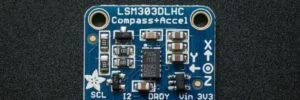
For this project, I chose to use the Triple-axis Accelerometer+Magnetometer (Compass) Board. This is a breakout board provided by Adafruit, which is built around the LSM303DLHC magnetometer + accelerometer sensor. The breakout board provides some very nice extra functionality including:
- A 3.3V regulator is included allowing you to power the device with 3.3-5V
- Data ready pin
- Two interrupt pins
- Integrated pull-up resistors
The sensor itself uses I2C communication protocol to send and receive data. Because I2C is highly dependant on the specific device, it was important to read the documentation for the LSM303DLHC.
I2C Communication
The PIC32 has two I2C peripherals, one of which I used to communicate with the magnetometer sensor. In order to use I2C communication, you have to open the peripheral by setting certain control registers. Using plib, this is as easy as a call to OpenI2C1( I2C_EN, BRG_VAL );. The SCL and SDA signals are connected to pins RB8 and RB9 on the PIC32. Once the module was initialized, I defined two helper functions for reading and writing data.
First, void i2c_write(char address, char sub_address, char *data, int num); takes in an 8 bit address, an 8 bit sub-address, a pointer to a character, and an integer number. The address information is used to select the proper device to communicate with. The data is treated as an array with the data to send. The number of bytes to send is defined by the final parameter num. To start, the address is OR’ed with the write signal, 0b00000000. This along with the sub_address is considered as the header. This is sent followed by the correct number of bytes from the array data.
Next, I defined a read function void i2c_read(char address, char sub_address, char *data, int num);. This function takes the same parameters as the write function. The 8 bit address and sub-address are treated the same, but know the bytes are read into the data array starting at data[0]. The parameter num is the number of bytes to read into the array. Reading data is slightly more involved than writing data using I2C. To start, the address is OR’ed with the write signal, 0b00000000. The sub_address is OR’ed with the auto increment signal, 0b10000000. Note, the auto increment functionality allows you to read multiple sequential sub-addresses in a row. This is most likely dependant on the specific device you are using. The two addresses are used as the header, and are written to the SDA line. Once the header is written, the restart signal is sent, and the same address is sent with a read signal attached, 0b00000001. Finally, following this we can read the requested data into the array.
LSM303DLHC Specific Implementation
I2C is highly dependant on the specific device you are trying to communicate with, therefore, it is important to note some specifics of communicating with the LSM303DLHC sensor. To begin, the breakout board from Adafruit has integrated pull-up resistors, so I could simply connect the SCL and SDA signal wires directly from the PIC32. In addition, Adafruit has developed a C++ library to use in conjunction with this sensor. I converted a large portion of this library to be compatible with the PIC32. In particular, the header file contains all of the required addresses and sub-addresses when using this sensor. The Adafruit code can be found here: Adafruit_LSM303DLHC. In order to begin receiving magnetic data from the sensor, some control registers must first be set. Setting the MR_REG_M register to 0x00 enables continuous conversion mode for the magnetic sensor. Next, setting the CRA_REG_M sets the minimum update rate for magnetic data. This can range between 0.75Hz and 30Hz. Lastly, I set the magnetic gain to a known value. Following this setup, I can now read data from the module. Although I did not implement this, it would not be too difficult to extend the code to read new data on every positive edge of DRDY. On the PIC32 this can be done using a change notice interrupt on a specific pin.
Heading Calculation
In order to calculate the angle heading of the sensor, you need the x and y magnetic field magnitudes. Using simple trigonometry, the heading is float heading = atan2f(y, x);. This result is returned in radians in the range -pi to pi. Therefore, it must be converted to degrees, and adjusted to range from 0 to 360.
Wifi
Overview
The last set of information that the drone must know in order to autonomously follow is something to follow. In this case, that will be a GPS signal from a phone. This requires some way for the drone to communicate with the phone. Bluetooth is a generally easy to implement but the range is not great. Because of this, I chose to use wifi to communicate with the drone remotely. In addition to sending GPS coordinates, I can send other control signals to the drone to change its flight.
Hardware Setup
For this project, I chose to use the Adafruit HUZZAH ESP8266 Breakout. This is a breakout board provided by Adafruit, which is built around the ESP8266 processor. This process is an 80 MHz microcontroller with a full WiFi front-end (both as client and access point) and TCP/IP stack with DNS support as well The breakout board provides some very nice extra functionality including:
- A 3.3V regulator is included allowing you to power the device with 3.3-5V
- Reset pin
- User button that can also put the chip into bootloading mode
The module itself uses UART communication protocol to send and receive data.
ESP8266 Code
The ESP8266 module can be used for a range of jobs and can be configured in many different ways. For my purpose, I simply wanted the device to act as a soft api to allow my phone to connect to its wifi. From here, I can open a TCP connection and send data to the module. As the last step, the data can be transmitted from the ESP8266 to the PIC32 using serial communication. In order to program the wifi module, I used the Arduino IDE. Configuring a soft api is as simple as a single function call, IPAddress myIP = WiFi.softAPIP();. Once this setup is successful, the host waits for a client connections. Once a connection is established, the server waits to receive data. When the line end is received, the data is serial transmitted from the TX pin.
App Code

In order to communicate with the wifi device, I had to write an application to send the required data. I have an android device, so I could easily develop and test an app using Android Studio. The image to the right is a screen shot of the main screen. The IP address and port number of the TCP connection must be specified. The green connected text means you have connected properly. When you are not connected, this will display red not connected text. The message text field is left over from my debugging and is now a feature! You can type a message into the field and send it to the wifi module using the send button. While it will be delivered, it is no guarantee that it will have any meaning to the wifi or PIC32. The three buttons Take Off, Land, and Stop, send various control signals to the wifi unit for the drone. Lastly, the three numbers at the bottom of the screen are the phones latitude, longitude, and altitude. They are currently 0.0 since the phone is not receiving any GPS data.
On the backend, the app will establish and maintain a TCP connection to the provided IP address and port number. When data is ready to be sent, it is written to the data stream, and received by the wifi module.
UART Communication
The PIC32 has two UART peripherals, one of which I used to communicate with the wifi module. On startup, I set peripheral pin select to map U2RX and U2TX to physical pins on the PIC32. My UART receive and transmit functions are similar to those defined by Bruce Land in the protothreads library. Both receive and transmit are actually protothreads to allow other threads to run while we are waiting on data. Because all of my transmitted messages are ended with CRLF, we continue to read in data until this is found, at which point we zero terminate the character buffer and return. In addition to this, we must continue to check for possible frame errors from the UART peripheral. If a frame error occurs, we discard the current message, and clear the error.
Flight Control
Overview
In order to actually control the drone, the PIC32 neeeds some way to communicate and send signals to the flight controller. This is where you really have to dive deep into the documentation of both the PIC32 and KISS flight controller to find a solution that works. Almost all current flight controllers will support multiple forms of communication as there are a range of different receivers on the markert since each one has its advantages over the other.
Communication Protocol
In general, most current drones rely on some form of serial communication with the receiver. For example, PPM acts as a summed PWM signal to support eight channels on a single wire. These protocols greatly reduce the complexity of the hardware since there is only a need for one signal wire in addition to ground and Vcc. Also, a larger number of channels can be supported than a protocol such as PWM for example which requires one input pin per channel. With all of these advantages, it might seem crazy for me not to go with a serial based communication protocol, however, that is exactly what I did. In particular, I used parallel PWM. Each channel has its own Pulse Width Modulated (PWM) signal on an individual wired connection. Most flight controllers including the KISS will support up to six channels using PWM (Pitch, Roll, Throttle, Yaw, Aux1, Aux2). The main driving factor behind choosing this protocol was the need for a killswitch. In trying to control the drone autonomously, I have very little control over its actions. If the PIC32 sends a throttle signal that is a little to large, I can easily lose my project off into the sky. Because of this, I needed some way to add a killswitch. The easiest way to add a killswitch is to use a standard drone receiver and transmitter. This functionality is often done in this way, and is easily supported on most frameworks. this difficulty with this is that it might be difficult or even impossible to use two different communication protocols on the flight controller. The advantage of PWM is that I have multiple signal wires. In this way, I can have the four main control signals (Pitch, Roll, Throttle, Yaw) controlled by the PIC32, and one of the other auxillary channels controlled by a PWM based receiver.
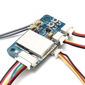
Killswitch Receiver
The image to the right is the receiver I used for this project. It supports PWM, PPM, and i-BUS. The eight wire connector in the bottom left of the image is the PWM bus. This can also be seen on the pinout to the left. For my purposes, I only needed three wires from the receiver; Vcc GND and one of the channels. For the specific channel, I chose to use channel 5. Generally, the first four channels are used for Pitch, Roll, Throttle, and Yaw, and five and six are auxillary channels. In conjunction with this receiver, I borrowed a Flysky transmitter from a friend, and set channel five to be controlled by one of the switches. Once I wired the channel 5 output from the receiver to aux1 PWM input on the KISS, I could receive the proper kill signal.
PIC32 PWM Signal
In order for the PIC32 to control the drone, I had to generate PWM signals for each channel I would like to affect. For this project, I control Pitch, Roll, Throttle, and Yaw using four separate PWM signals from the PIC32. In Betaflight you can change various minimum and maximums regarding the input pulses, but most signals will follow a fairly common standard. Betaflight defines two constants, rx_min_usec = 885 and rx_max_usec = 2115. These define the minimum and maximum pulse lengths in microseconds which are considered valid by the flight controller. However, in general most signals will range between 1000 and 2000 microseconds. In my PIC32 code, I limited my pulse lengths to fall within this range. As far as the frequency of the PWM pulse train, almost any frequency is acceptable. Many receivers seem to use a frequency of 50 Hz. This is rather slow, and a large clock divider is required to acheive this frequency. The increased clock divider decreases the resolutin of the pulse length giving you less ability to make fine adjustements. Because of this, I increased my frequency to 200 Hz. This can be achieved using a peripheral bus clock of 40 MHz, a clock divisor of 4, and a timer counter of 50000. Then, in theory, the pulse width in microseconds will be pulse_width_value / 10. The image to the left is a trace of one of the PWM signals. This particular pulse train has a pulse width of 1500 microseconds, which is defined as mid_rc in Betaflight.
Once I was able to generate the proper PWM signals, I tried to pass them to the KISS flight controller. In working on this, I encountered a few interesting bugs. First, all channels have a defined fail mode defined as rxfail in Betaflight. By default, the first four channels are set to automatic failsafe mode. In this case, when the signal data is not within the valid range, the channel defaults to a particular value. For Pitch, Roll, and Yaw this default value is mid_rc, while Throttle defaults to rx_min_usec. The auxillary channels default to a different failsafe mode, hold. In this mode, when an invalid signal is received, the last valid value is used. In order for the PIC32 signals to be properly received, the channels must be in hold mode. Once I changed this for the first four channels, the PIC32 signals could be seen in the receiver tab of Betaflight.
The next issue I encountered was the mapping from the KISS’ PWM input pads was different from the internal pin mapping. For example, the solder pad labeled as Throttle on the KISS affected the Pitch value in Betaflight. This is not a critical issue as I just need to know the correct mapping, but there is a fix to map the corresponding pads with their signals. In Betaflight, you can change the channel mapping. The two main provided mappings are AETR1234 and TAER1234. For the KISS, the mapping must be changed to 1TAER234 to match the solder pads. Once I had these issues fixed, I wired up all of the signals including the auxillary receiver channel and tried to arm the flight controller. A few notes must be made about arming as I encountered issues. First, I defined a range of values for channel 5 which would arm the flight controller. Even if this is satisfied, the flight controller might not arm. First, the Throttle must be below a certain value. In Betaflight, this is defined as min_check, and was set to 1100. In order to fix this, I set the Throttle channel output from the PIC32 to rx_min_usec. In addition to this, if any of the first four channels are not receiving valid data, it will not arm. There are some other small reasons why it might not arm. If the cpu load is too high, you have to decrease it by decreaseing the PID loop. Also, you might have to calibrate the accelerometer or ensure the flight controller is sitting stable on a level surface. Once I had satisfied all of the requirements, I was able to arm the flight controller. Taking the propellers off of the motors, I tested the communication between the PIC32 and flight controller. Once the flight controller was armed, I could increase the speed of the motors by adjusting the Throttle PWM.
PIC Setup

Overview
A lot of consideration had to go into the setup and wiring of the PIC32. Trying to make an autonomous drone, the PIC32 must be attached to the drone and be able to operate on whatever power is provided. I went through a couple different design choices and ultimately settled on a solution which works well. In addition to the physical setup, I had to develop code which would work in the new environment.
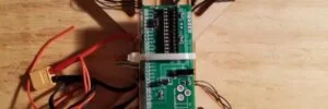
PIC32 Wiring
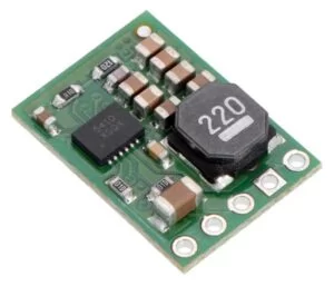
After some thought and experimentation, I decided to build the small developmemnt board to hold the PIC32. Although this is the largest board I had to fit on the drone, it is was manageable. Using standoffs, I was able to place the ESC, KISS flight controller, and PIC32 in a stack centered on the drone. The next biggest issue I had to deal with was how to power the drone. I could pretty easily jump power from the battery since I was already using it to power the flight controller and ESC. However, the voltage on battery packs can be fairly large compared to what the small board voltage regulator can handle. Initially I thought I wanted to use a large battery which would have a voltage of overe 20V. Evenutally, I settled on using a 3S battery whihc outputs around 11V. I still chose, however, to get another voltage regulator to support larger voltages. I ended up using a Pololu 5V 1A D24V10F5 regulator which can take an input voltage of up to 36V. This easily satisfied my requirements. The output voltage of this regulator was then passed to the large board and eventually stepped down to 3.3V. Once I had the small development board wired up, prior to adding the PIC32, I connected the battery and measured the voltage to ensure everything operated as expected and nothing exploded. ***Note, remember to flip the switch on the board to the on position. Otherwise you will spend a couple minutes wondering why you are not getting any voltage, like me.
After the PIC32 was wired up to get power, I could begin wiring the signal connections. RA0, RA1, RA2, and RA3 were used as PWM channels for the flight controller. The KISS can recognize 3.3 V logic, so these signals did not have to be changed and could passed straight to the flight controller. I did not have to add a ground connection between the PIC32 and KISS since they already have a shared ground from the battery. Each of the extra modules (GPS, Compass, wifi) required at minimum four connection to the PIC32. Power and ground could be jumped from the PIC32 development board. Because each breakout board has its own voltage regulator, any of them can receive 5V or 3.3V. In addition to this, both communication protocols I used require to connections. For UART, I connected the TX and RX pins to the opposite one on the other device. For I2C, I connected the SCL and SDA lines.
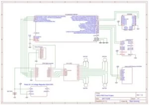
Schematic
Here is a full circuit schematic for the drone I built.
Software
This project required a lot of software to communicate with the various peripheral devices. First, two UART peripherals were used to communicate with the GPS and wifi units. The description of these can be found in their respective sections. At a high level, I had two protothreads which continue to read in data and update global variables with the parsed information. This is also done with the magnetometer, but the communication protocol is I2C rather than UART.
For the PWM signals, I used four different output compare units. These were rather easy to configure. On startup, I open the modules, and initialize them with a default value. For pitch, roll, and yaw this value was mid_rc whereas for throttle this value defaulted to 1000 microseconds. The flight control was then updated in a timer interrupt service routine. Timer 2 is setup to run at 100Hz. On each pass through, the PWM width is adjusted to fly the drone.
Results
Drone
I began by assembling and testing the drone framework. In order to add any autonomous flight, I had to ensure I had a solid basis. This started in Betaflight. Once I had the flight controller and ESC wired together and to the motors, I could perform a motor test in the GUI. Increasing the power to each motor, I could figure out my mapping and rotation. Luckily all of my motors were set up perfectly. I did not have to remap anything, or change the direction of rotation.
Following this, I added a small serial base receiver to test the flight of the drone with a transmitter. This behaved as expected and was quite a large milestone. Seeing drone fly, even if being controlled was a large part of the project.
PWM Control
Next, I had to ensure I could control the flight controller with the PIC32. After setting up the code to generate the PWM pulses and wiring the connections to the flight controller, I tested the signals in the Betaflight GUI. In the receiver tab I could see changing signals as I changed the PWM pulse width. There is a video in the videos section showing my testing of the killswitch. This was highly dependant on the flight controller receiving proper signals.
External Modules
Once I had all of the code to receive data from the GPS, compass, and wifi modules, I tested it using the big development board. Using the big board, I could display the messages being received on the TFT display and ensure the data make sense.
FLIGHT!!!!!!
After testing the previous sections, I could finaly test the drone running from the PIC32. I did this by arming the drone and increasing the throttle to get the drone to fly up. Initially, I was highly dependant on the killswitch as I was investigating various throttle values. After the first few values barely lifted the drone off of the ground, I increased the throttle to a fairly large value. When the drone finally took off, it shot up to the ceiling of the room. I hit the killswitch right away, and managed to catch the drone. Thankfully, the only damage to the drone were a few bent signal pins. After fixing this, I continued to play with the control values. Taking the drone outside for one flight, it ended up getting too high and too far away. I had to hit the kill switch, and the drone crashed to the ground. Once of the drone arms broke, and I had to quickly cut a new frame and transfer all of the hardware. After fixing the drone, I resumed testing, and it behaved as expected.
In testing the flight of the drone, it became apparent that it is very difficult to maintain a constant altitude. Typically, drones will use sonar, or a barometer to acheive altitude hold. While it is possible to add one of these to my drone build. There was next to no documentation with the flight controller I used. Because of this, I resolved that it would take more time than I had and decided not to pursue it further. Without an easy way to perform altitude hold, it was difficult to work on a following algorithm. Although I had developed communication with the GPS and compass modules, I decided not to include them in the final build.
Source: Autonomous Drone
- Why did the author choose to use an existing flight controller instead of building one?
The author chose an existing controller to avoid the complexity of PID tuning and stability issues, allowing focus on high-level inputs. - How does the drone communicate with the user's phone?
The drone uses an Adafruit HUZZAH ESP8266 breakout board to establish a Wi-Fi connection that accepts TCP data from a custom Android app. - What communication protocol is used between the PIC32 and the GPS module?
The PIC32 communicates with the GPS module using UART to receive NMEA sentences containing position and velocity data. - Why was parallel PWM selected over serial protocols like PPM for flight control?
Parallel PWM was chosen to implement a killswitch using a standard receiver on an auxiliary channel while the PIC32 controlled the main four channels. - What material was used to construct the drone frame?
The frame was laser cut from 5mm wood to allow for cheap and rapid prototyping. - How is the drone's heading calculated?
The heading is calculated using trigonometry based on the x and y magnetic field magnitudes read from the LSM303DLHC magnetometer. - What voltage regulator was used to power the PIC32 development board?
A Pololu 5V 1A D24V10F5 regulator was used to handle input voltages up to 36V from the battery pack. - Why was altitude hold not implemented in the final build?
Altitude hold was omitted because there was next to no documentation available for adding barometers or sonar to the specific KISS flight controller used.