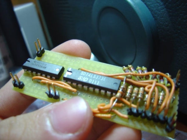
So I needed a DAC (digital to analog converter) to use with my pic12F675 , and for those of you who have never heard of this little fella, it’s an 8 pin microcontroller from Microchip that has only 6 I/O pins…

This is a very simple circuit that converts Digital data (serial input) to Analog values ranging from 0v to 5v (I used it to generate audio (adding an output capacitor to filter DC) with the 12f675 (requires amplification) )
It can also be used as a serial->parallel output multiplexer (see digital outputs)
Materials:
+(1) 74164 8bit Shift Register
+(1) 74373 8bit Latch
+(9) 10K resistors
+(7) 4.7K resistors
+’Generic’ perfboard (the pcb…)
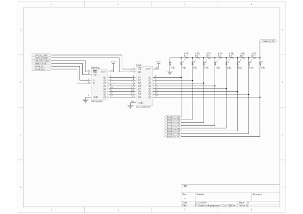
Step 1: The Schematics

I was thinking of using this as a generic DAC ( “plug and play” at any breadboard(plugboard) ) for most applications you won’t need to use all inputs (but DON’T let them float)
Inputs :
tri_state :
‘1’ will put the digital outputs to tri-state (while in tri-state the digital “outputs” can be used as parallel input to the DAC)
‘0’ Normal Usage
Latch_Enable :
‘0’ Maintains the current Register state (Maintains the current analog output)
‘1’ Copies the inputs from the shift register and stores it
Not_Shift_clear:
‘0’ Clears the Shift register
‘1’ Normal Usage
Shift_Clock:’
__/ clocks the result of the expression (Serial_In and Serial_In2) into the shift register
Outputs:
Analog_Out: after all It is a digital to ANALOG converter…
Parallel_Out 0-7: but it’s also a output multiplexer =D
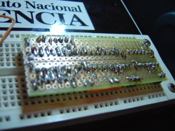
Step 2: The Assembly As a Breadboard ‘Plugin’

By using this cheap perfboard and adding some “(Jumpers)-1″ My DAC is now a single (unusually LARGE) component …
My assembly isn’t particularly elegant…but it does the trick…
