Summary of 2-Axis Gesture-Controlled Camera Platform
This article details a 2-axis gesture-controlled platform for DSLR cameras, enabling accurate remote pointing via joystick or IMU hand gestures. The system supports heavy cameras (3kg+), achieves sub-3-degree error, and responds within 3 seconds. It features three control modes: joystick velocity, IMU velocity, and IMU angle positioning. The project integrates mechanical assembly, servo actuators, Hall effect sensors, and custom software on a PIC32 microcontroller to manage motor control and camera functions like auto-focus and shutter release.
Parts used in the 2-Axis Gesture-Controlled Camera Platform:
- PIC32 Microcontroller
- Arduino Nano 33 BLE Sense
- Two high torque servo motors
- Continuous rotation servo
- Hall Effect Angle Sensor
- Diametrically magnetised magnet
- Joystick controller with push buttons
- 9 DOF IMU
- Multi-functional gesture sensor
- npn BJT transistors
- 5.4mm laser-cut clear acrylic sheet
- Aluminium rotating bearing
- Bevel gears
- Digital proximity sensor
- Ambient light sensor
Introduction
For the ECE 4760 final project, we designed and implemented a 2-axis gesture-controlled platform for DSLR cameras. The platform can actuate a camera based on the orientation of the user’s hand with relative high accuracy and low latency.
Our 2-DOF gesture-controlled platform can point the camera in any direction within a hemi-sphere based on spherical coordinates. It is capable of rotating continuously in horizontal direction and traversing close to 180 degrees in vertical direction. It is able to support a relatively large camera system (more than 3kg in total weight and 40cm in length), orient the camera accurately (error less than 3 degree), and respond quickly to user input (transverse 180 degrees in less than 3 seconds). In addition to orienting the camera, the system also has simple control functionality, such as allowing the user to auto-focus and take photos remotely, which is achieved through DSLR’s peripheral connections.
At a high level, our design supports three user input modes – the first one uses a joystick while the other two use an inertial measurement unit (IMU). In the first mode, the x- and y-axis of a joystick is mapped to the velocities in the yaw and pitch directions of the camera. In the second mode, the roll and pitch angles of the user’s hand are mapped to the velocities of the camera in the yaw and pitch directions, while the third mode mapped the angles to the angular position of the camera.
Our general design workflow involves outlining individual components of the system based on requirements, writing test codes for each component, designing and manufacturing the platform based on the mechanical characteristic of the camera, integrating the actuators and sensors, testing the system for accuracy and responsiveness, and making any further adjustment to the code.
We have also made a video demo of our project. 2-Axis Gesture-Controlled Camera Platform
High Level Design
Inspiration
Our design is inspired by the observation that holding a professional DSLR camera during a long photo-shooting event, such as a hockey game or air show, is usually very tiring. Furthermore, the accuracy for which the photographer can track the object with the camera always tends to decrease as he or she becomes tired. Therefore, a platform that allows the photographer to accurately control the camera without directly holding it would be a helpful accessory. However, most of the existing platforms that accomplish such goals are either too expensive, i.e., multiple-DOF robot arm, restricted in their available motions, i.e., can only stabilize the camera, follow pre-programmed sequences, controlled by joysticks, or limited in the supportable camera due to mechanical or electrical constraints. Therefore, we would like to design such a camera controller that is accurate, low-cost, multifunctional, easy to manufacture, and intuitive to use.
Mathematical Background
To use IMU as a user interface, we need to extract information about the pitch, roll, and yaw angles from the sensor readings. The following diagram illustrates the three angles of interests. Source: Wikipedia
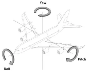
We can calculate the pitch and roll angles based on the readings of the accelerometer as following:
float pitch = 180 * atan2(x, sqrt(y * y + z * z)) / PI;
float roll = 180 * atan2(y, sqrt(x * x + z * z)) / PI;
where x, y, and z are the readings from the three axes. The resulting pitch and roll angles have range -90 to 90 degrees. To reduce noise from the vibration of the user’s hand, a low-pass filter could be applied to the calculated angles.
Logical Structure
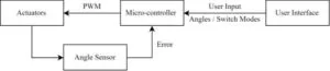
The following schematic shows the overall logical structure of our design. The microcontroller takes inputs from the user to determine the target orientation of the camera, possibly with commands to switch control modes. Then, based on the error between the target position and current position given by the angle sensor, the microcontroller sends a PWM signal to the actuators, with the goal of reducing the error.
Hardware/Software Trade-off
To simplify the software interface between the PIC32 and IMU, which uses I2C protocol, an Arduino device might serve as an intermediary. After retrieving the sensor data from IMU, the Arduino could send the readings to the PIC32 through serial. However, this might create extra delays for the data to reach the microcontroller, which influences the responsiveness of the system.
Hardware Design
Mechanical Assembly
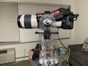
Considerable efforts were put into the design and manufacturing of the mechanical assembly to ensure that the platform is able to support a heavy DSLR camera. The following two images show the finished assembly with and without the camera mounted. The major structural support of the assembly is made of 5.4mm laser-cut clear acrylic sheet. All servo motors, power supply, and control circuits rotate together with the platform so that no wire will be entangled during the rotation. The lower part of the platform consists of two layers – the lower layer is mounted to a aluminium rotating bearing, while the top layer is mounted above it with 45mm spacer in between. The top part of the platform consists of two vertical stands, with the camera rotating in between.
Actuators
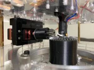
Two high torque servo motors are used as actuators in the camera platform. The bottom servo, which is shown below, is a continuous rotation servo. Mounted to the top part of the assembly, it rotates the whole platform continuously using a set of bevel gears.
The top servo shown below has a 180 degree range. It is directly connected to the square camera mount. The design of the square bracket ensures that the center of gravity of the camera is approximately aligned with the rotation axis of the top servo, which minimizes the torque.
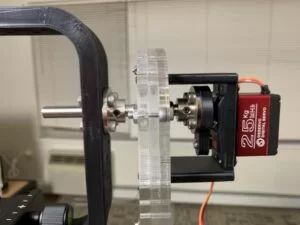
Hall Effect Angle Sensor
A 360 degree analog hall effect angle sensor is used to monitor the orientation of the rotation platform. It is placed near the bottom servo (shown above), right above the larger bevel gears. There is a diametrically magnetised magnet on top of that bevel gears. The magnet and hall effect sensor is approximately 2mm apart, as required by the sensor specification.
User Interfaces
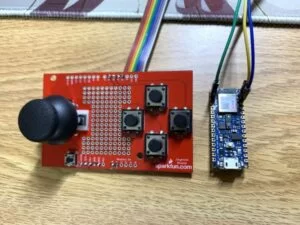
Two types of user interface are provided. The first one is a hand-held controller with a joystick along with several push buttons. The x and y axes of the joystick are mapped to the angular velocities of the camera in yaw and pitch directions respectively. The buttons are used for focusing the camera, releasing the shutter, adjusting the panning speed, and switching control modes. The second interface is an Arduino Nano 33 BLE Sense, which has a built-in 9 DOF IMU and a multi-functional gesture sensor. It communicated with the PIC32 through Serial. The two types of interface are shown below.
Interface to Camera
Most DSLR cameras provide a connector for external shutter release. There are typically 3 wires – GND, shutter signal, and focus signal. Auto-focusing and shutter release are enabled by shorting the corresponding wire to ground. In our design, such functionality is achieved using npn BJT, with the base connected to a digital output pin. Details are shown in the appendix.
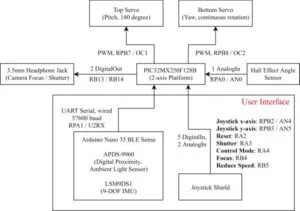
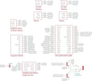
Overall Block Diagram with PIC32 Pin Connections
Software Design
Control Mode
We implemented three control modes for this project – mode 0: Joystick, mode 1: IMU Speed, mode 2: IMU Angle. In mode 0, the platform is controlled by a joystick which changes the angular velocity of the camera based on the position of the joystick. The x- and y-axis of the joystick is mapped to the velocities in the yaw and pitch directions respectively. In mode 1, the roll and pitch angles of the user’s hand are mapped to the velocities of the camera in the yaw and pitch direction. A larger tilt angle of the hand will result in a higher angular velocity. In mode 2, the roll and pitch of the hand directly correspond to the target yaw and pitch of the camera. As a result, when the user’s hand is stationary, the camera will move to the target orientation and stabilize at that angle. The full range of motion achievable by mode 2 is 180 degrees in both directions. Please refer to the demo video in the beginning.
ISR
The ISR in our main code computes and sets the duty-cycle for servo PWM based on the current control mode. Variable servo_p is the control signal for the top servo with a range of 0 – 1023. Variable servo_r is the control signal for the bottom servo with a range of 312 – 1562. The ISR runs at 50Hz (20ms interval), and the range of duty-cycle 312 – 1562 corresponds to an on-time of 0.5ms – 2.5ms, as specified by the servo documentation. The following flowchart shows the overall structure of the ISR.
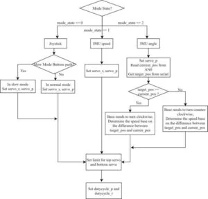
The joystick mode contains two speed modes. When the button on the controller connected to RB5 is pressed, the angular velocity of the platform is reduced to 25%, which allows for a more accurate position control. In mode 2, the duty-cycle of the bottom servo motor depends on the relative position of the current angle and target angle. The servo will turn slower as it approaches the target. This prevents the camera from overshooting the target and eliminate vibrations around the target angle. Please refer to the comments in the code attached in the appendix.
Protothread_mode
In the mode thread, we set PT_YIELD_TIME to 50 msec. We switched mode in this thread if the mode button(RA4) pressed and the button was not pressed in the previous cycle. For example, the mode_state is 0, when the mode button is pressed but was not pressed in the previous cycle, we switched the mode_state to 1.
In mode 0 (Joystick), if the shutter button (RA3) is pressed, the camera will release the shutter and take a picture. If the focus button (RB4) is pressed, the camera will turn on the auto-focus.
In mode 1 & 2, if the serial command serial_shutter is true the shutter will be released; if the serial command serial_focus is true then auto-focusing will be turned on.
Protothread_serial
We used serial command to establish the communication between the Arduino Nano 33 BLE sense and the small board. The messages sent by Arduino are patterns matched against a single letter command followed by an integer value. There are three types of serial messages. The message starts with character ‘p’ is the pitch angle of the hand; the message starts with ‘r’ is the roll angle of the hand; the ones that start with ‘s’ indicate shutter status – when the cmd[0] is ‘s’, set serial_shutter and serial_focus to true if the value is 1, set serial_shutter to false and serial_focus to true if the value is 0, otherwise, set serial_shutter and serial_focus to false.
Arduino Nano 33 BLE Sense
The Arduino board reads the data from the IMU, calculates the pitch and roll angles, converts them to an integer from 0 – 999, and sends the data to PIC32 through serial. It also determines the camera control signal based on the position of the user’s finger. If the finger is above the digital proximity sensor, the sensor will output 0 and the auto-focusing will be turned on though serial command; if the finger is covering the sensor, the ambient light sensor will read close to 0 in all three color channels and the shutter will be released through serial.
Results
The final assembly of our 2-axis camera platform was tested against a 3.6kg camera system with zoom lens. The assembly is able to turn the camera with reasonable stability. To test the accuracy and responsiveness of the platform, the system was put into IMU angle mode. The average settling time from the current orientation to target orientation is measured using a digital timer. To test the accuracy, the measured angle of the camera was compared with the desired target orientation print out by the Arduino to serial monitor. The angle in yaw direction was measured against a marked reference angle on the base of the platform using a protractor. The angle in pitch direction was measured using a smartphone’s built-in angle sensor by placing it parallel to the lens. The average error is 1.5 degree in pitch direction and 2.8 degree in yaw direction. The average settling time is 2.91 seconds.
Conclusions
For the final project, we designed and implemented a 2-axis gesture-controlled platform that can actuate a camera based on the orientation of the user’s hand. The performance, i.e., accuracy and responsiveness, of the design mostly met our expectations. However, there are multiple ways through which we can improve the project. In our original proposal, we planned to use bluetooth for the communication between the Arduino board and the PIC32. The Arduino board we used is very versatile since it packs a microcontroller, multiple sensors including IMU, and a bluetooth module in a very small package. However, since it is using a unique protocol for Bluetooth 5.0, we failed to establish the bluetooth connection with the PIC32. We’ve also considered using two Arduino boards of the same type. However, this created delays in the communication that is intolerable. Therefore, to achieve the wireless functionality, we could consider using a different board on the sensor end.
In addition, most of the errors in the yaw direction were caused by the loose mechanical coupling between the two bevel gears. A redesign of the support structure for the bottom platform could potentially solve the issue. Furthermore, the loose coupling makes implementing a more sophisticated controller for the bottom servo very hard since the behavior of the gear is unpredictable. In our current implementation of mode 2, the bottom servo was never put into full power to prevent overshooting and oscillation around the target position.
Schematic
- What is the maximum weight the platform can support?
The platform supports camera systems weighing more than 3kg in total. - How many control modes does the system offer?
The system implements three control modes: Joystick, IMU Speed, and IMU Angle. - Can the camera rotate continuously in the horizontal direction?
Yes, the platform is capable of rotating continuously in the horizontal direction. - Does the system allow for remote auto-focusing and photo capture?
Yes, users can remotely trigger auto-focus and take photos using peripheral connections. - What is the average settling time for the camera to reach a target orientation?
The average settling time is measured at 2.91 seconds. - How is the accuracy of the pitch direction measured?
The pitch angle is measured using a smartphone's built-in angle sensor placed parallel to the lens. - What caused the errors in the yaw direction?
Most errors in the yaw direction were caused by loose mechanical coupling between the two bevel gears. - Why was Bluetooth communication not used between the Arduino and PIC32?
Bluetooth was not used because the unique protocol for Bluetooth 5.0 prevented establishing a connection with the PIC32. - How does Mode 2 handle the camera movement when the user's hand is stationary?
In Mode 2, the camera moves to the target orientation and stabilizes at that angle when the hand is stationary. - What component is used to monitor the orientation of the rotation platform?
A 360 degree analog hall effect angle sensor is used to monitor the platform's orientation.