
Summary of 100MHz frequency counter with PIC16F628A – LCD Display
This project builds a simple 100MHz+ frequency counter using a PIC16F628A microcontroller, a 32768Hz watch crystal for a 1s time base, and a high-speed comparator for signal conditioning. Timer0 counts the input pulses on RA4, Timer1 provides the accurate time base, and an adaptive prescaler with a 0.125s gate yields 1Hz resolution below 1MHz. Input protection, power regulation, and soft ON/OFF using MOSFETs are included. The comparator TLV3501 conditions signals into clean 0–5V pulses. The firmware is written in C and compiled with MikroC for PIC.
Parts used in the 100MHz+ frequency counter:
- PIC16F628A microcontroller
- 32768Hz watch crystal resonator (X1)
- Capacitors C4 and C5 (33pF–62pF range)
- High-speed comparator TLV3501 (Texas Instruments)
- Input protection resistor R1 (1k) and optional low-frequency input resistor 47k
- Diodes for input clamping (to ±0.7V)
- Voltage regulator LM78L05 or LM2931-5.0
- P-channel MOSFET (soft ON/OFF)
- N-channel MOSFET (soft ON/OFF latch)
- LCD display with backlight and resistor R9 for brightness control
- Pushbutton for power ON/OFF
- Power source (9V battery or 7–20V DC)
- Optional 50 Ohm input resistor for VHF range
This project shows how to build a very simple yet very useful tool that every DIY enthusiast should have in his lab: a 100MHz+ frequency counter.
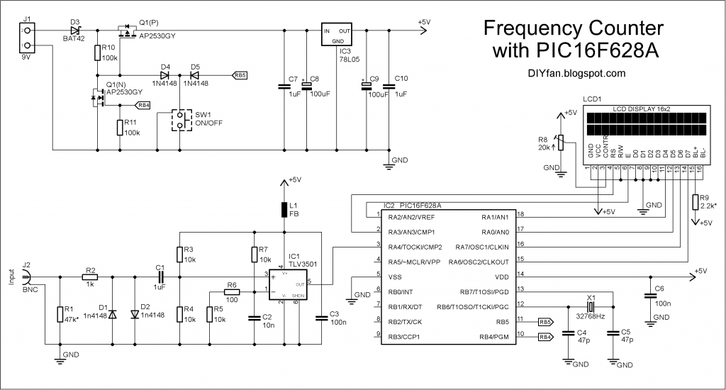
The schematic is fairly simple and straightforward and uses a PIC16F628A microcontroller for measuring frequency and a high speed comparator for signal amplification and conditioning.
The microcontroller uses its internal 4MHz oscillator for the CPU clock. Timer1 uses an external crystal resonator (watch crystal) with 32768Hz frequency for setting the 1 second time base.

Timer0 is used to count the input signal at pin RA4.
The max frequency of Timer0 is 1/4 of the CPU clock which is 1MHz, but there is internal prescaler and it can be set from 1 to 256. In theory this can allow the input signal to be up to 256MHz. On the other hand, in the datasheet of 16F628A there is a requirement for the input pulse at RA4 to be with minimum width of 10ns which is 100MHz frequency. So the maximum frequency can be between 100Mhz and 256MHz. I checked with two different PIC16F628A and they easily go over 200Mhz barrier.
In order to achieve the maximum possible resolution, the input signal is probed for 0.125 seconds and the prescaler value is computed accordingly. This way when input frequency is below 1Mhz the resolution will be 1Hz.
The most important part for the accuracy of the frequency counter is the time base setting circuit – crystal resonator X1 and capacitors C4 and C5. C4 and C5 values can be between 33pF and 62pF and the crystal frequency can be fine tuned with them.
The input of the schematic is feed through a high speed comparator. In order to switch with 100+ Mhz frequency the comparator must have propagation delay bellow 5ns. In this schematic I used Texas Instruments TLV3501 with 4.5ns delay. This was cheapest high speed comparator I was able to find (2.5 euro).
The two inputs of the comparator are set at about 1/2 of power supply voltage with 15-25mV difference between them so any AC signal with higher voltage will start switching the comparator.
If there isn’t input signal the output of the comparator stays low. If we connect a signal source to the positive input, when the signal goes over +20mV the comparator switches high (5V), when signal goes bellow +20mV comparator switches back to 0V. So whatever signal we fed to the input, the output is square wave 0V-5V with the same frequency as the original signal.
The output of the comparator is fed directly to the RA4 pin of the microcontroller.
The input is protected with 1k resistor and two diodes limiting the voltage to ±0.7 V. The input impedance for low frequencies is equal to R1 – 47k. For VHF range maybe it is good idea to replace it with 50 Ohm value.
The schematic can be powered by 9V battery or any other DC voltage from 7V to 15-20V. LM78L05 or LM2931-5.0 IC is used for regulating the voltage down to 5V. There is simple soft ON/OFF circuitry with a dual P- and N-MOS transistor. When button is pressed the P-MOS transistor is switched on and the microcontroller is powered and its first instruction is to set RB4 high which switch the N-MOS transistor on and the power stays on. If the button is pressed again RB5 goes low and the microcontroller sets the RB4 low and this way switch the power off. The microcontroller also auto switch the power off after a certain amount of time (3min 40sec).
The schematic have fairly low power consumption – with no input signal the supply current is 7-8mA and goes up to 20mA with 200+MHz input signal. If the display is too dark, the back light can be adjusted by decreasing the value of the R9 resistor. This of course will increase the current consumption.
The program for the microcontroller is written in C and is compiled with MikroC for PIC
Schematic
For more detail: 100MHz frequency counter with PIC16F628A – LCD Display
- What microcontroller is used in the project?
The project uses a PIC16F628A microcontroller. - How is the 1 second time base generated?
Timer1 uses a 32768Hz watch crystal resonator and capacitors C4 and C5 to create the 1 second time base. - How is the input signal conditioned before reaching the microcontroller?
A high-speed comparator (TLV3501) amplifies and square-waves the input, producing 0–5V pulses fed to RA4. - What is the purpose of the input protection components?
A 1k resistor and two diodes clamp the input to about ±0.7V to protect the comparator input. - What frequency range can the Timer0 count theoretically and practically?
Theoretically up to 256MHz with prescaler, but the PIC16F628A requires input pulse width ≥10ns, so practical maximum is between 100MHz and 256MHz; the author measured over 200MHz. - How is high resolution achieved for low frequencies?
The input is measured for 0.125 seconds and the prescaler is computed accordingly so frequencies below 1MHz achieve 1Hz resolution. - Which comparator propagation delay is required for 100+ MHz operation?
The comparator should have propagation delay below 5ns; TLV3501 with 4.5ns delay is used. - How is power supplied and regulated for the circuit?
The circuit can be powered from a 9V battery or 7–20V DC and uses LM78L05 or LM2931-5.0 to regulate to 5V. - How does the soft ON/OFF power control work?
A pushbutton turns on a P-MOSFET to power the microcontroller, which then latches power via RB4 driving an N-MOSFET; pressing again or an auto timeout causes RB4 to go low and power off. - What is the typical power consumption?
With no input signal the supply current is 7–8mA and it rises to about 20mA with a 200+MHz input signal.
