This instructable describes how to integrate hobby servos (the kind used in RC planes, cars, etc.) into your microcontroller projects.
Step 1: How Servos are Different from Regular Motors
In a regular DC motor, the amount of torque the motor exerts on the shaft is proportional to the amount of current flowing through the motor. A simple way to control it is by varying the voltage across the motor; more voltage means more current which means the motor pushes harder against its load which means the shaft turns faster.
When using a servo, however, you don’t control torque or velocit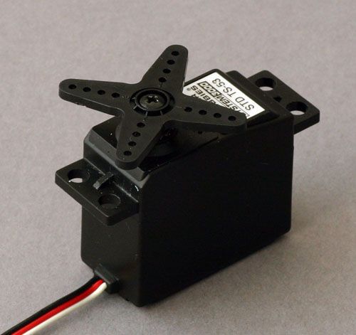 . Instead, you specify what angle you want the shaft at. In other words, you have positional control of the motor.
Inside a servo is a traditional DC motor, a potentiometer (variable resistor), and control circuitry. The potentiometer is connected to the motor such that when the motor shaft turns it also turns the potentiometer. The controller can then measure the voltage at the center pin of the potentiometer and get an indication of the shaft’s position. The controller receives a signal (see next step) from the user that sets a desired position. The controller compares the desired position to the current position of the motor and uses that information to turn the motor in a direction that minimizes the error.
The way this works in practice is you specify the angle you want the shaft at using your PIC, the shaft turns to that position, and then holds there. The further it gets pushed away from that position, the harder it tries to turn back. Hobby servos are usually geared way down, so even a wimpy $15 or $20 one can hold its position reasonably well.
Step 2: The Control Signal
In addition to power (red wire, 5 volts works fine) and ground (black wire) connections, the servo accepts a control signal on the third wire (usually white or yellow). The signal is almost pulse width modulated, except that it doesn’t have a fixed period.
It is composed of pulses of voltage, the duration of which determine the angle of the output shaft. The pulses can be from 0.9 ms to 2.1 ms long, 1.5 ms being the center position (in other words, pulse duration varies linearly with shaft angle). I don’t remember whether 0.9 ms means all the way clockwise or all the way counter clockwise, but it’s not a big deal to test our your project, see that the servo is turning the wrong way, and reverse it in your code. A new pulse must be sent to the servo once every 10 to 20 ms (50 to 100 Hz).
These timing/voltage values are for a typical servo. You should be able to find documentation for you specific servo from the manufacturer.
Step 3: The Circuit
This schematic is actually from something else, but it’s ridiculously similar to the one I’ll use for a quick demonstration.

The only change that needs to be made for this project is to replace the LED and its resistor with the wire for the control signal. So instead of connecting pin 3 to a resistor and then to an LED and then to ground, just connect pin 3 to the white/yellow wire from the servo. The ICD2 block represents the PIC programmer I used, substitute your own if you want. Also, don’t forget to hook up the servo’s power and ground connections.
For more detail: Use a PIC Microcontroller to Control a Hobby Servo