Summary of USB 0-500MHz RF Power Meter with AD8307 using pic microcontoller
The AD8307 USB 0-500MHz RF Power Meter efficiently measures RF transmitter power from 1nW to 2W, extendable to 50W with an attenuator. It uses the AD8307 IC and a PIC18F2550 microcontroller to sample power levels and communicates results to a PC via USB, avoiding the need for an LCD. The device supports auto-ranging across various power units and operates over a 0-500 MHz frequency range. The power meter probe connects directly to the transmitter output, while the USB IO board handles USB communication and power management.
Parts used in the AD8307 USB 0-500MHz RF Power Meter:
- PIC18F2550 Programmed Microcontroller
- AD8307 RF Power Meter IC
- RF Power Meter Probe PCB
- USB IO Board PCB
- USB Type B Connector
- 20MHz Crystal Resonator
- 470K Resistor (yellow purple yellow gold)
- 10K Resistor (brown black orange gold) x2
- 100 Resistor (brown black brown gold) x2
- 470nF Ceramic Capacitor
- 100nF Ceramic Capacitor x5
| AD8307 USB 0-500MHz RF Power Meter Component List: | 1x PIC18F2550 Programmed Microcontroller
1x AD8307 RF Power Meter IC
1x RF Power Meter Probe PCB
1x USB IO Board PCB
1x USB Type B Connector
1x 20MHz Crystal Resonator
1x 470K Resistor (yellow purple yellow gold)
2x 10K Resistor (brown black orange gold)
2x 100 Resistor (brown black brown gold)
1x 470nF Ceramic Capacitor
5x 100nF Ceramic Capacitor |
|
|
|
| | Technical Specifications: | |
|
|
 AD8307 USB 0-500MHz RF Power Meter
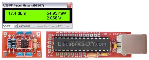
Measurement of transmitter output RF power has never been easier and more precise. AD8307 USB 0-500MHz RF Power Meter allows to measure the power of transmitters from 1nW to 2W / 50W with 40dB attenuator. Output is displayed in dBm, Watts (nW, uW, mW and W range) as well as input voltage. USB RF Power Meter is based on popular AD8307 watt meter IC and PIC18F2550 microcontroller. Instead of using LCD display module the meter connects to a PC via USB port and displays measurements on a computer via USB RF Power Meter software. The software settings can be changed to use 10-50dBm attenuator and thus allowing to measure RF power higher than 2W.
AD8307 RF Power Meter Probe
AD8307 RF Power Meter Probe is used to measure the strength of RF power and may be mounted in a small metal enclosure. To measure output RF power of transmitter connect AD8307 probe input directly to the output of your transmitter (antenna output). AD8307 probe should be connected to USB IO Board by using three wire cable. The three wires provide power for the probe that is drawn from USB port through USB IO Board, ground wire and output that connects to PIC18F2550’s PIN2 (A0).
 USB IO Board
 USB IO Board is used to sample voltage from AD8307 chip and pass the information in a digital format to a PC via USB port. The board consists of very few components; mainly PIC18F2550 microcontroller, standard USB Type B connector, breadboard compatibille PCB, 20MHz crystal resonator, two capacitors and two resistors.
 AD8307 USB 0-500MHz RF Power Meter
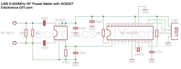 USB IO Board