A very popular type of LED that has finally come about is the tri-color, RGB LED. The RGB stands for: red, green and blue since the LED is capable of displaying all three colors, independently. This means that an RGB LED can display any color of the rainbow. This is a powerful capability, but it also requires more control.
In this article, we shall look at how to build an RGB LED controller so that we have accurate and independant control over all three colors at any instant. The method of Fading LEDs via PWM will be leveraged for this design, since our goal here is quite similar, but with more control paths.
Purpose & Overview of this project
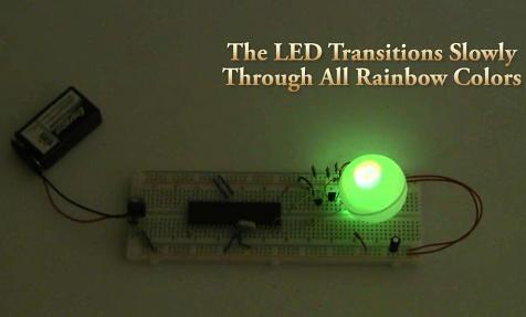
The purpose of this project is to build an RGB LED controller that can display all the colors of the rainbow is a slow, but methodical motion. A microcontroller should be used with 3 digital outputs. An interrupt timer routine will be used to keep track of elapsed time, along with counters to know what duty cycle the PWM control should be outputting.
The PIC 18F452 will be used as the microcontroller of this project with a 40 MHz crystal clock. Running this fast will allow the microcontroller a greater resolution of control for the PWM’s duty cycle. A common-cathode high intensity RGB LED will be used with 3 2N2222 general purpose transistors to control switching when the R/G/B portions of the LED should be connected to power or ground.
40 MHz Crystal
PICkit2
7805 +5v Regulator
4x 10kΩ Resistor
7x 100Ω Resistor
47uF Capacitor
RGB LED
3x 2N2222
Breadboard
Wires
SIPS
9v Connector
Battery Holder
Parts List Details
The parts used in this project are virtually the same as with the Fading LEDs via PWM article, we’ll use a few more 2n2222 tranistors, resistors and an RGB LED instead of a standard 1 color LED.
PIC 18F452
This microcontroller built by microchip will serve as the intelligent device for our system, controlling the RGB LED at our will. It will run at a 40 MHz crystal clock speed, which is the maximum for the PIC18F452.
7805 +5 Voltage Regulator
This +5v regulator will be used create the power supply source for all of the electronics used in this circuit. Since the circuit is very small the actual load placed on this regulator will be small, maybe 100 miliamp.
PICkit 2
The PICkit 2 is a programmer for the Microchip PIC microcontroller and it has a legacy for being one of the best, even with the 3rd version already available. You will need some programmer to get your programs onto the PIC and this is the one that I suggest.
2N2222 General Purpose Transistor
This 2N2222 transistor will be used to control the LED state between on and off. The transistor will be connected directly to the microcontroller which will send a signal telling the transistor what state it should be in: on or off.
RGB LED
This is the common-cathode RGB LED. It has 4 wires coming out of it. The longest wire is the ground pin. The other 3 wires connect to the anode of the Red, Green and Blue LEDs. You can test each portion of the LED by connected a 100Ω resistor a power source (9v battery) and the ground pin to ground.
Jumper Wires & Breadboard
I prefer to use a breadboard with the projects in my articles because they offer maximum flexibilty with circuit design with minimal downtown between changes. In addition to the breadboard you will need jumper wire to get everything connected together.
Schematic Overview
The schematic for this tutorial was kept as simple as possible so that the focus could remain on how the touch screen works and how we interface to it. You can see the completed schematic for this project below. The main parts in the schematic are the RGB LED, 18F452 and LM7805.
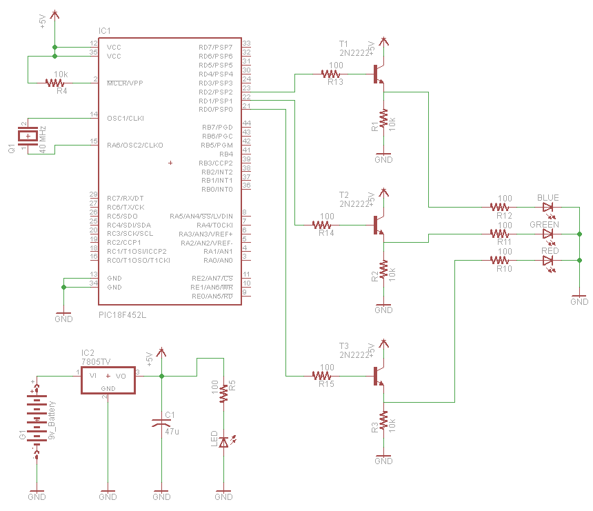
Schematic Specifics
Power Regulator
The power regulation circuit is a LM7805 +5v regulator that will convert the +9v from the battery to a steady +5v output to the PIC.
PIC Microcontroller Circuit
The microcontroller circuit consists of the PIC 18F452, it’s 40 MHz crystal clock and the 10k resistor connected to pin 1, MCLR. Along with power and ground connections, these are the basic connections necessary to run the program loaded on the PIC.
For more detail: RGB LED Controller using PIC18F452