
Summary of Making your own Digital Clock using PIC16F887
This article describes a small, single-sided LED dot matrix development board designed for testing programs. The author notes that while the breadboard version worked, the custom PCB failed to function despite correct assembly. The board features an SMD footprint and measures 58.4mm by 46mm.
Parts used in the Small LED Dot Matrix Development Board:
- LED dot matrix display
- PIC16F887 microcontroller (SMD version)
- SMD components
- Single-sided PCB
Small LED dot matrix development board
I was very busy for the past two months so this blog just didn’t move.
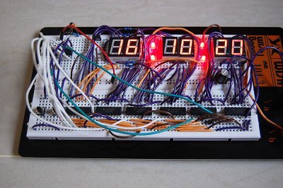
As you may know, the LED dot matrix display is my favorite device. I have designed a small development board for testing my led dot matrix related programs.
The PCB is single sided so I can make it at home. Most of the components are SMD to keep small footprint of the board. The PCB size: 58.4mm x 46mm
The schematic is as the following:
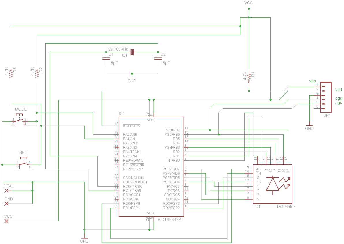
Acutally, I made a PCB and installed all components but the board didn’t work :p. It was working when I tested the schematic on breadboard (with through hole version of PIC16F887).
For more detail: Making your own Digital Clock using PIC16F887
- Why did the author design this board?
The author designed it to test LED dot matrix related programs. - What type of PCB was used for the project?
A single-sided PCB was used so it could be made at home. - How large is the developed board?
The PCB size is 58.4mm x 46mm. - Why were most components chosen as SMD?
SMD components were used to keep the footprint of the board small. - Did the custom PCB work immediately?
No, the board did not work after installation. - Which component version worked on the breadboard?
The through hole version of the PIC16F887 worked on the breadboard. - Where can I find details about making a digital clock using this chip?
Details are available in the article Making your own Digital Clock using PIC16F887.
