In a previous article I described how I designed the circuitry to control functions of the asparagus harvester. After bread boarding up a test circuit and doing some initial programming I decided a re-do was in order.
I found I had a lot of unnecessary redundancy and I also decided to put the air regulation function on a separate chip from the main controller chip. I did so because I want the air regulation to be continuous and it looked like programming the original chip to handle that and everything else would require more programming expertise than I have. I’ll throw in a 12F675 dedicated to the air regulation.
Review of the functions of the controller for the harvester:
Turn on electronics when hydraulic pressure is present.
Enable air valves only when machine is moving forward at a minimum speed.
Provide adjustment for fine tuning the cut timing.
Provide air pressure regulation for the toolbar/manifold
Sound alarm if air pressure drops below pre-set point.
Sound alarm in case of a cylinder fault.
Provide driver with up switch to raise header for making turns at the end of the field.
Control the hydraulic header lift cylinders so the header floats 9″ above the bed.
Raise the header rapidly in case of a cylinder fault.
Buffer the shaft encoder and send to optics board
Outputs
Hydraulic lift cylinder “slow” valve Up Solenoid
Hydraulic lift cylinder “slow” valve Down Solenoid
Hydraulic lift cylinder “fast” valve Up Solenoid
Hydraulic lift cylinder “fast” valve Down Solenoid
Alarm Horn
B+ for air valve solenoids
Encoder signal for optical board
Output for air regulator valve
Inputs
Up proximity switch – open collector output
Down proximity switch – open collector output
Driver pendant up button – momentary contact to ground
Driver pendant down button – momentary contact to ground
Shaft Encoder output – open collector output
Photo electric switch – cyl. fault detector – open collector output
Air pressure transducer – 0 to 5 volt = 0 to 250 psi analog output
B+ from Hydraulic Pressure Switch
Explanation of the circuit
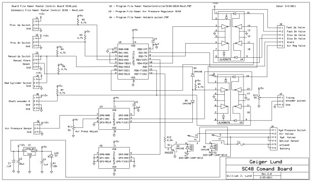
Refer to the schematic below for the explanation which follows immediately below the schematic.
Click on the schematic to get a BIG version.
Nearly all of the actual functions performed are done in software in the two microcontroller chips. Most of the circuitry is for interfacing the inputs and outputs to the microcontrollers.
First we will examine the inputs and outputs and what interfacing is implemented. All of the inputs and outputs use screw terminals.
J1 and J2 are 3 terminal connectors for the bed height sensing proximity switches. Each connector supplies ground and +12 volts for the sensors and provides a 5.1 k pull up resistor for the open collector outputs.
J3 is a 4 terminal connector for the tractor driver’s pendant which has a push-button to raise the header quickly and a push-button to lower the header at the end of his turn or to reset a cylinder fault. It provides a ground, two terminals for the up button and one terminal for the down button. The second up button is a spare because we may want’ to ad an up button for the sorter as well as the driver.
J4 is a 3 terminal connector for the photo electric switch that detects cylinder faults. The connector provides ground and 12 volts dc for the switch, and the signal terminal ties to the up switch on J3.
J5 is a 4 pin terminal, with two ground terminals, (ground and shield), 12 VDC, and signal pin tied to a pull up resistor. The signal pin ties to the input on one of the ULN2067B darlington drivers for buffering as well as the 16F627 microcontroller.
J6 is a 3 terminal connector supplying ground, 12 VDC, and a signal pin for connecting to the pressure transducer. The signal pin does not require a pull up resistor. The output of the transducer is an analog 0 to 5 volt output.
J7 is a 3 terminal connector for sending the buffered encoder signal and the cut timing voltage to the optical board. It has a ground pin, encoder out pin, and dc 0-5 volt analog signal pin. The 0 to 5 volt dc timing signal pin connects to the wiper of a 5 k resistor connected between +5 volts and ground forming a simple variable voltage divider. The buffered encoder out pin connects to the UL2067B darlington logic driver.
J8 is a 6 pin connector providing outputs for the fast and slow hydraulic lift cylinder valve solenoids, the alarm horn, and the air regulator valve. The inputs of the darlingtons are directly driven by the microcontroller pins except for the encoder pulses which come directly from the shaft encoder.
J9 is a 6 pin connector which has two terminals for connection to the battery and a terminal for the hydraulic pressure switch. It has output pins providing the B+ for the optical sensor and hydraulic valves.
The terminals that connect to the battery connect to a fuse on the circuit board that provides the 12 volts to power the circuit board itself, the air valve power, the hydraulic valve power, the and all the devices that need 12 volts.
The alternator needs a field connection to the battery to begin putting out voltage. This is accomplished by having a hydraulic pressure switch connect the positive terminal of the batter to the field. The same connection from the field side of the switch also goes to the hydraulic pressure switch terminal where it drives relay K2s coil directly. Relay K2 provides a connection from the fuse to the terminals supplying B+ to the optical board, alarm horn, hydraulic valves and to the relay that powers the air valves.
The relay that powers the air valves is driven through a 2N222 transistor which is driven directly by an output pin on the 16F627. Both relays have a suppression diode across the coil.
The 12 volts from the battery that passes through the fuse and then through relay k2 then travels on to a 3 terminal +5 volt regulator, along with the appropriate bypass and filter caps to provide 5 volts for the microcontroller chips U2 and U3 and all of the pull up resistors.
Chip U2 provides the functions of keeping the header at a pre-determined height above the bed, enabling the air valve B+ supply only when the machine is moving forward, raising the header rapidly if there is a cylinder fault or the up button is pushed on the tractor driver pendant. It also provides an alarm signal for several seconds when the header is raised rapidly. The darlington used to drive the horn is connected to the chips output pin through a diode so that the air regulating chip can be wire “or’d” to the same darlington input.
Chip U3 Provides the air regulation function and sounds the alarm horn if the air pressure drops too low. A pot is connected from ground to +5 volts with the center lead connected to the analog to digital converter in the chip to obtain an air pressure set point.
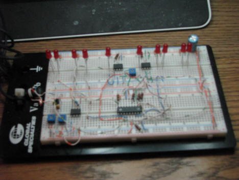
Here is a picture of my breadboard setup for programming the chips. All of the outputs from the chips go to the LEDs and I just used jumper wires for the inputs and pots for the analog inputs.
For more detail: Re-Doing my Design for a circuit to control an invention using a Microchip PIC microcontroller chips.
