Programmable relays find use in numerous automation applications such as automatic street light control, watering and pump control, HVAC, home automation, power plants automation in industries, etc. This article describes how to build a fully functional, one-channel programmable relay switch using the PIC16F628A microcontroller. It allows you to set both ON and OFF time. The maximum time interval that you can set for on and off operations is 99 hours and 59 minutes. Another interesting feature of this project is it offers cyclic option, which means you can choose to run it in a continuous loop of ON and OFF cycles. The device can be programmed through 4 push switches. The programming menu and device status are displayed on a 16×2 character LCD. The timing resolution of this relay timer is 1 minute. The timer also saves the user inputs to its internal EEPROM so that it can retain these values after any power supply interrupt. Here are the summary of the features that this timer device has:
- Microcontroller powered timer switch
- OFF and ON time setup for the relay operation
- Option for cyclic run
- ON/OFF timing range: 0 to 99 hours and 59 minutes
- 1 minute timing resolution
- Interactive user interface using 4 tact switches and a character LCD
- Buzzer alarm
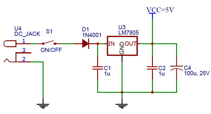
- On-board +5V voltage regulator
Circuit diagram
The hardware part of this project is very simple. The entire circuit runs off a regulated 5V power supply derived using the popular LM7805 linear regulator chip (Figure 1). To minimize the heat dissipation in the voltage regulator, the recommended input DC voltage to LM7805 is 9V, which can be easily obtained from a DC wall adapter. Diode D1 (1N4001) is used for reverse polarity protection in the circuit. S1 is a slide switch for turning the power supply on and off.
Figure 2 depicts the input and output setup. There are five tact switches in this project: one for microcontroller reset, and four for user inputs. The four input switches are named as Menu/+, Select, Enter, and Start/Stop. Their functions will be described in the software section. The status of the 4 input switches is read by the PIC16F628A microcontroller through ports RA2, RA3, RA4, and RB0. The output LCD is a standard HD44780-based display and is driven in 4-bit mode. The pin assignments for the LCD data and control signals are shown in Figure 2. S2 is another slide switch that allows manual control of the LCD backlight.
The output relay switch is driven through a NPN transistor (2N2222). The project also includes a DC buzzer that beeps when the relay switch changes its status. The relay and buzzer circuits are shown in Figure 3.
The PIC16F628A microcontroller runs at 4.0 MHz using an external resonator. The I/O pins of PIC16F628A, the resonator connection, and the in-circuit serial programmer (ICSP) header are shown in Figure 4.
For more detail: PIC16F628A Programmable Digital Timer