
Summary of 00 to 99 minute timer using PIC16F628A microcontroller
This article presents a simple PIC16F628A digital timer project capable of timing up to 99 minutes. The author shares the source code and circuit diagram as a beginner-friendly practice exercise, utilizing an HD44780 LCD for display and tact switches for input control. Although the original hardware was lost, the functionality is demonstrated using a DIY breadboard module where an LED replaces a relay to indicate the active state.
Parts used in the Digital Timer Project:
- PIC16F628A microcontroller
- 4.0 MHz external crystal
- HD44780 based 16×2 character LCD
- Three tact switches (Start/Stop, Unit, Ten)
- DIY PIC16F628A breadboard module
- Experimenter's I/O board
- LED
Last week I was browsing my old backup hard drive and I found a source code for a very simple PIC based digital timer that I made a couple of years ago. The actual hardware of the project isn’t with me anymore. I might have lost it when I moved from my old apartment into my new home. However, I thought this might be a good practice project for beginners and so I am sharing it here. I am not going to build it from scratch again; I will rather demonstrate it using my DIY PIC16F628A breadboard module and I/O board. The complete circuit diagram along with the firmware developed using mikroC Pro for PIC compiler is provided in the article.
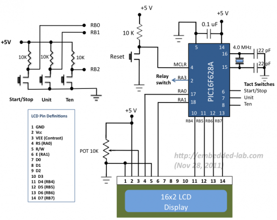
Circuit diagram
As I mentioned earlier, the microcontroller used in this project is PIC16F628A running at 4.0 MHz clock using an external crystal. An HD44780 based 16×2 character LCD is the main display unit of the project where you can watch and set the timer duration using tact switch inputs. There are three tact switches connected to RB0 (Start/Stop), RB1 (Unit), and RB2 (Ten) pins. You can select the timer interval from 0-99 min using Unit and Ten minute switches. The Start/Stop switch is for toggling the timer ON and OFF. When the timer gets ON, a logic high signal appears on the RA3 pin, which can be used to switch on a Relay. The circuit diagram of this project is described below.
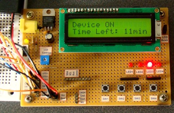
I am using my self-made breadboard module for PIC16F628A and experimenter’s I/O board here to demonstrate this project. Since there is no relay switch in the I/O board, I am connecting the timer output (pin RA3) to an LED. When the timer starts, the LED is turned ON. As the timer duration is elapsed, the LED is turned OFF.
For more detail: 00 to 99 minute timer using PIC16F628A microcontroller
- What is the maximum time duration this timer can measure?
The timer allows users to select an interval from 0 to 99 minutes. - How does the user set the timer value?
Users select the timer interval using two specific switches labeled Unit and Ten minute switches. - Which pins are assigned to the tact switch inputs?
The three tact switches are connected to RB0, RB1, and RB2 pins respectively. - What signal appears on pin RA3 when the timer starts?
A logic high signal appears on the RA3 pin when the timer gets ON. - Can this circuit be used to control a relay?
Yes, the logic high signal on RA3 can be used to switch on a Relay. - What compiler was used to develop the firmware?
The firmware was developed using mikroC Pro for PIC compiler. - How is the timer output demonstrated in the article?
An LED is connected to the timer output to turn ON when the timer starts and OFF when the duration elapses. - What clock speed does the microcontroller run at?
The PIC16F628A runs at a 4.0 MHz clock using an external crystal.
