Summary of Lets Program a PIC Microprocessor
This article provides a beginner-friendly guide to programming a PICAXE 08M2 microprocessor, emphasizing starting simple by flashing an LED. It details assembling the circuit on a breadboard, explains the pin configuration, connects power, LED, and resistor, and guides using the PICAXE programming editor and USB cable for downloading BASIC code. The tutorial stresses careful wiring, power limits, and offers simple example code to make the LED blink. It also suggests experimenting with multiple LEDs, Morse code, and sound commands to enhance learning.
Parts used in the PICAXE 08M2 LED Blinking Project:
- PICAXE 08M2 microprocessor
- Small breadboard
- LED (any color)
- 330 ohm resistor
- Picaxe Breadboard programming adapter AXE029
- USB programming cable
- 3-cell battery box with switch
- Breadboard jumper wires
- PC or Mac with Picaxe program editor software (free)
OK How hard can programming a PIC microprocessor be?
Well it depends, some are harder than others for several reasons, The programming language, the type of microprocessor, the ease of use of the editing software and most importantly how familiar you are with it all.
So lets look at one of the easiest to handle (in my opinion) The PICAXE system.
Whenever we get questions here on programming I always say the same thing, START simple, learn to get an LED flashing, play around a bit with the hardware so you get used to how it is connected together, understand what your trying to do.
To follow what I have done here you will need:
A PICAXE 08M2 microprocessor – £1.80
A small bread board (just for ease of connection) – £3.36
An LED any colour – £0.05 I use green but the colour isn’t important
A 330 ohm resistor – £0.60 (for 100)
For ease of connection the Picaxe Breadboard programming adapter AXE029 – £2.39
A USB programming cable – £11.99
A 3 cell battery box £0.89 – I like the ones with a switch on them.
And the Picaxe program editor for PC or MAC – Free.
All of the above can be bought from the Picaxe shop if your in the UK for the prices quoted above
http://www.picaxestore.com/index.php/en_gb/picaxe….
Or look on their web site as they have numerous USA and other dealers that carry their products.
http://www.picaxe.com/Distributors
I also use some pre made bread board connection wires, these I bought from Amazon but you can find them in many places.
http://www.amazon.co.uk/Ecloud-Shop-Solderless-Fle…
Step 1: BREAD BOARD 101
If your not familiar with using bread board then hopefully this will help.
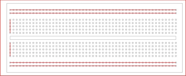
The bread board is a plastic board with many holes in it.
A close look at it (or at the picture above) will show you these holes are grouped, in two lines left to right at the top and bottom and in sets of 5 holes vertically in between.
The holes are interconnected as shown on the diagram in red.
The two sets top and bottom are connected left to right.
The sets of 5 holes are connected vertically.
The gap in the middle is to allow you to position your ICs so each leg of the IC is in a separate vertical line of holes above and below the gap. See other picture as we go along.
Using the holes you can connect components together as if they were wired.
This is very useful for experimentation as you can pull things out and replace then easily as often as you like.
The down side is that many people get confused and put a connection into the wrong set of holes so watch and double check what you are doing all the time (this is easier then trying to fault find afterwards.)
Step 2: Starting With the Microprocessor.
The Picaxe family contains around 15 or so different microprocessors, the main difference is some are bigger than others and have more legs, thus an 08 has 8 legs and the 40 has – 40 ! this means the 40 can make more connections than the 08 (and is more expensive) you choose a microprocessor according to the task you have and how many inputs and outputs you need.
For our experiment we will only need the 08M2.
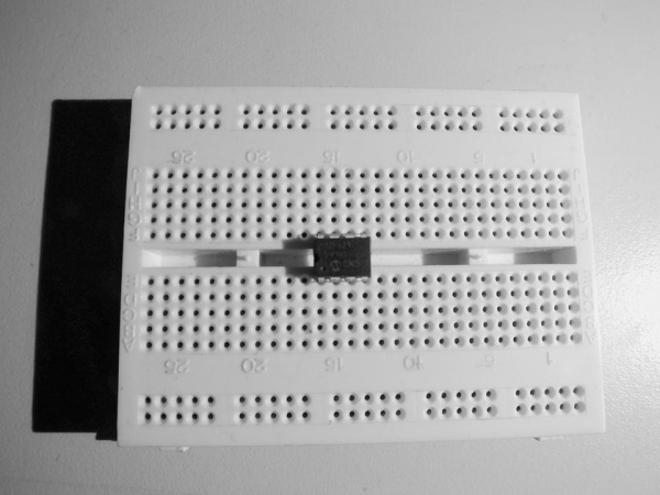
As you can see in the picture above the Picaxe 08M2 has 8 pins, at the top there is a Notch and there may be a small dot or circle by the side of leg 1.
Not all IC’s will have the dot but all will have the notch, holding the IC with the notch at the top will mean leg 1 is at the top left.
The legs then number sequentially round the IC.
We must place the IC so it is set across the gap in the bread board. Legs above and below the gap and the notch to the left side. So leg 1 is at the bottom just as in the picture above.
Each leg has a specific purpose.
Leg 1 is + 5 volts – the power for the IC
Leg 2 is the programming leg (input)
Leg 3 is a digital input or output
Leg 4 is a digital input
Leg 5 is a digital input or output
Leg 6 is a digital input or output
Leg 7 is the other programming pin
Leg 8 is 0 volts (or the negative side of the battery)
NOTE:
Confusingly for most people the legs are numbered differently internally for programming purposes.
So PICAXE refer to the programming PINS and to the real world LEGS.
The pin allocation can be seen in the diagram above.
Step 3: Connecting the Power Legs
We need to connect Leg 1 to +v and leg 8 to neg
We can do this with a small jumper wire. I like to use ready made jumpers as they are easier and last a long time.
If you use wire then ensure it is solid core or it won’t go into the holes.
I have chosen to use the inner of the 2 top and bottom lines but you can use either.
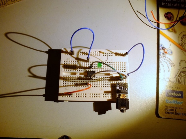
Step 4: Connecting the LED
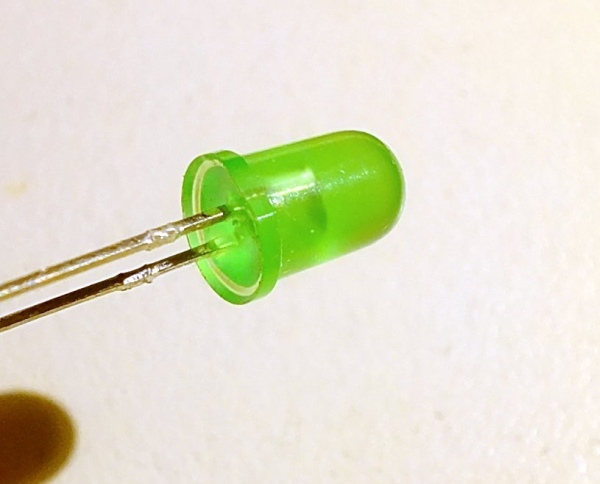
The LED will if you look very closely have a flat section at the bottom of the coloured case.
This looks like a minus sign, (to me), and so the wire closest to the flat is the NEGATIVE side of the LED.
As illustrated in the image above.
The LED will be connected to leg 6 (this is programming pin 1)
We will connect the positive side of the LED (NOT THE FLAT) to leg 6 and push firmly into a hole in the same line as the leg 6 is in.
The other negative end we will put into an unused set of 5 holes elsewhere on the board it doesn’t matter which you select.
An LED has to have it’s current limited or it will burn out so we need to put a 330 ohm resistor between the negative wire and the negative supply line. Look carefully at the picture above.
Resistors are colour coded, we don’t need to go into this now but the 330 ohm resistor will have bands on it that are Orange, Orange and brown.
This value resistor will limit the current to a fairly small value and prevent the LED burning out.
Step 5: The Programming Adaptor.
the Picaxe microprocessor is far too small to connect a screen or keyboard to so we will use a PC or MAC to do the programming.
Picaxe provide a FREE programming tool on their web site so down load it onto your PC.
NOTE:
You don’t need any hardware to start programming, the program editor has a built in simulator for all of the Picaxe microprocessors so you can write a program and run it without needing to buy anything else.
BUT that isn’t really much fun or more to the point at some time your going to want to start building that autonomous surveillance robot or servant and for that your going to need the hard ware.
To connect the PC and the microprocessor you will need to buy, (or make if you have a serial port on your PC), a down load cable. I suggest you buy the USB cable you can obviously use this over and over again so you only ever buy one.
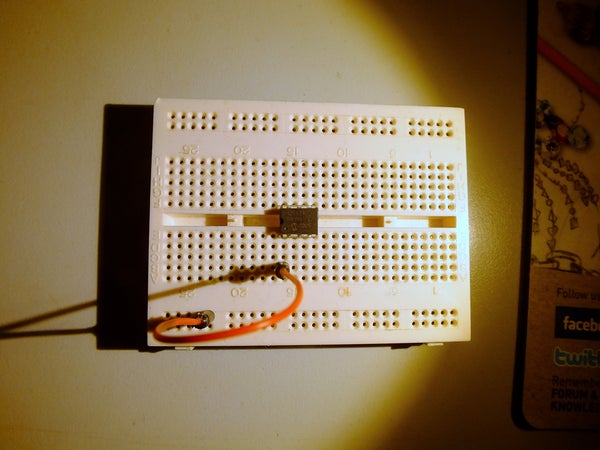
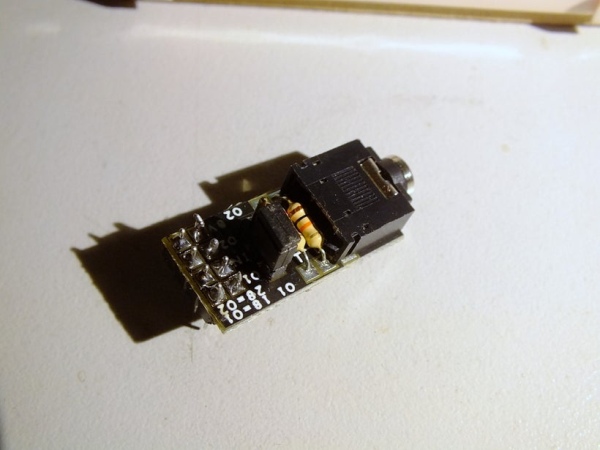
.To make connecting the down load cable to your bread board easier I strongly suggest you buy a bread board adapter this makes things so much more reliable.
I place the adapter in one corner of the bread board to keep it out of the way.
The adapter has to be connected to 0 volts and to the transmit and receive pins on the Picaxe 08M2 – the illustration shows these connections.
Step 6: Power Supply
The Picaxe 08M2 uses a + 5 volt maximum supply.
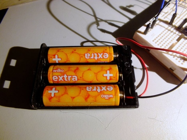
I strongly suggest that initially you use batteries in a battery holder with a switch on it to make turning on and off easier.
Buy a 3 cell battery box, this will give you 4.5 volts which is within the range of the Picaxe 08M2.
IF you use 4 cells then your connecting 6 volts to the Picaxe and this is out of range and the chip may get hot and fail. So 3 cells is good or a 5 volt regulated power supply.
I cut a couple of the connectors off a jumper wire and soldered then onto the battery box to make this connecting easier.
Step 7: Programming
OK the really hard part!
Learning a foreign language isn’t fun for most of us and many of the microprocessors out there use C++, python, ETC which although very modern languages have some peculiarities that make their programs hard to read at first. Picaxe however use a language developed in the 1960s called BASIC (Beginners All purpose Symbolic Instruction Code) This is MUCH more like English and easier to understand.
In fact for most of what you may try to do for the first few months you only need to know 6 of the 120+ commands available. (Phew).
In computers you tend to use 0 meaning OFF and 1 meaning ON
You also see High meaning On and LOW meaning OFF
SO 1=HIGH=ON
0=LOW=OFF
The command High C.1 will turn programming pin 1 on and make it go to 5 volts.
The command Low C.1 will make it go off and go to 0 volts.
The C refers to the internal port inside the Picaxe 08M2 and this full address is required for this device. The advantage is that more or less all input and output pins can be reconfigured but that is too advanced at present
The microprocessor works very quickly – it will process about 10,000 lines of programming code a second!!
So to see thing happen, like an LED flashing, we need to slow things down to a human level.
The command Wait will wait for a pre set number of seconds, so Wait 1 is one second, wait 5 is 5 seconds etc.
The Picaxe program will need to know where some parts of the program start, this is indicated by using labels.
A LABEL is any word that is not reserved as a programming command.
You must follow the Label with a colon to show it is a label.
to jump to a label you use a command GOTO (label name). You will see below that in our program we use goto Start to get back to the start of the program and run it all again.
SO,
For flashing our LED we now know all we need.
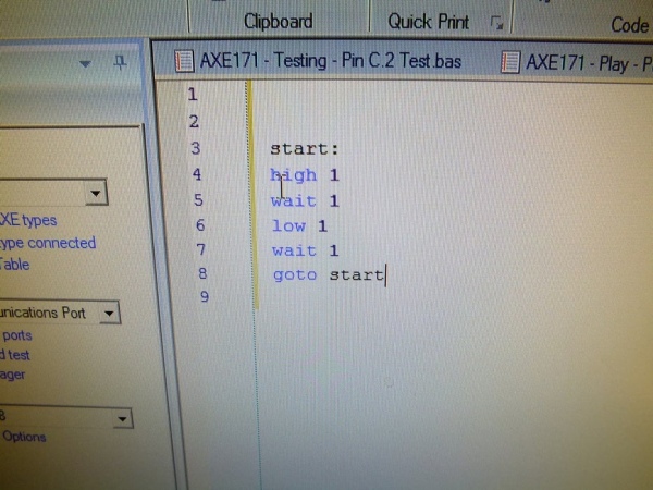
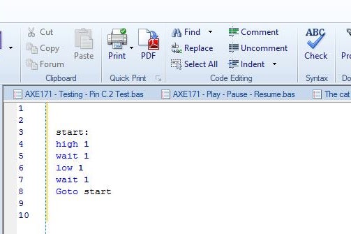
The program will look like this:
Start:
High C.1 turns output 1 on
wait 1 waits for 1 second
low C.1 turns output 1 off
wait 1 waits for 1 second
Goto Start jumps to the label start to do it all again.
Step 8: Doing the Programming
You have downloaded the program editor from the Picaxe site.
You have built your circuit as described earlier.
You have double checked all connections are correct IN PARTICULAR the battery connections are + to LEG 1 and negative to LEG 8 If you connect these the wrong way round the Picaxe microprocessor will get HOT and possibly be damaged.
Connect the programming cable to the USB port and to the Adapter on the bread board.
Open the Picaxe program editor and to make sure everything is OK on the editor screen at the top left corner you will see in Blue “Check Picaxe type connected” (as in picture above)
Select this with your mouse and turn on the battery box, the editor should report back the type of picaxe it finds. if it can’t find one then you will need to see why.
Frequent faults.
1. No power to Picaxe.
2. Transmit and receive connections from adapter swapped or missing.
3. Down load cable not plugged in.
4. Correct USB port not selected in the editor.
5. Adapter has a ground connection to the negative side of the battery.
PROGRAM
Assuming you get the right message then you ready to program.
Write the program as described already in the editor. Use a separate line for each command it will make things clearer.
Assuming the editor hasn’t any problems with your program, it will check it and try to tell you where the fault is. Remember that computers are very picky and need their commends to be in exactly the right format or syntax. spelling and lack of spaces are the most often errors.
If in doubt refer to the Picaxe web site and go to the manuals, down load the PDF file for the BASIC commands and look up the syntax for your command.
Select program, (see picture above), and then turn on the battery pack. At the lower right corner or the screen you should see the green download bar progress from left to right.
Once the program is down loaded it should run automatically and the LED should flash once a second.
IF it doesn’t work then check:
1. Power
2. The LED is connected to LEG 6 on the IC
3. the resistor and LED negative side are in the same set of holes
4. The LED is the right way round.
5. Turn power Off and On again this restarts the program.
6. Battery isn’t flat.
7. Battery polarity is correct, +ve to Leg 1.
8. battery negative is connected to Leg 8.
The video above shows It working.
Step 9: Other Things to Try

OK it is the next day for me and I thought i might add a few more things you might do with this simple set up by altering the code.
However no clues here that is up to you to figure out.
1. Add a couple more LEDS and flash them.
2. Flash the LED long on short off.
3. Flash morse code SOS is easy – – – . . . – —
4. Look up Charlieplexing and add a lot more LEDS and make a Knight rider warning.
5. Look in the manual and check out the tune command. It’s easy. If you play one of the built in tunes to an LED it will flicker like a candle.