16×2 Character LCD is a very basic LCD module which is commonly used in electronics projects and products. It contains 2 rows that can display 16 characters. Each character is displayed using 5×8 or 5×10 dot matrix. It can be easily interfaced with a microcontroller. In this tutorial we will see how to write data to an LCD with PIC Microcontroller using Hi-Tech C Compiler. Hi-Tech C has no built in LCD libraries so we require the hardware knowledge of LCD to control it. Commonly used LCD Displays uses HD44780 compliant controllers.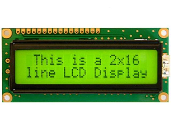
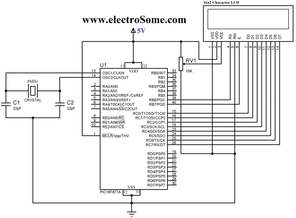
This is the pin diagram of a 16×2 Character LCD display. As in all devices it also has two inputs to give power Vcc and GND. Voltage at VEE determines the Contrast of the display. A 10K potentiometer whose fixed ends are connected to Vcc, GND and variable end is connected to VEE can be used to adjust contrast. A microcontroller needs to send two informations to operate this LCD module, Data and Commands. Data represents the ASCII value (8 bits) of the character to be displayed and Command determines the other operations of LCD such as position to be displayed. Data and Commands are send through the same data lines, which are multiplexed using the RS (Register Select) input of LCD. When it is HIGH, LCD takes it as data to be displayed and when it is LOW, LCD takes it as a command. Data Strobe is given using E (Enable) input of the LCD. When the E (Enable) is HIGH, LCD takes it as valid data or command. The input signal R/W (Read or Write) determines whether data is written to or read from the LCD. In normal cases we need only writing hence it is tied to GROUND in circuits shown below.
The interface between this LCD and Microcontroller can be 8 bit or 4 bit and the difference between them is in how the data or commands are send to LCD. In the 8 bit mode, 8 bit data and commands are send through the data lines DB0 – DB7 and data strobe is given through E input of the LCD. But 4 bit mode uses only 4 data lines. In this 8 bit data and commands are splitted into 2 parts (4 bits each) and are sent sequentially through data lines DB4 – DB7 with its own data strobe through E input. The idea of 4 bit communication is introduced to save pins of a microcontroller. You may think that 4 bit mode will be slower than 8 bit. But the speed difference is only minimal. As LCDs are slow speed devices, the tiny speed difference between these modes is not significant. Just remember that microcontroller is operating at high speed in the range of MHz and we are viewing LCD with our eyes. Due to Persistence of Vision of our eyes we will not even feel the speed difference.
Hope that you got rough idea about how this LCD Module works. Actually you need to read the datasheet of HD44780 LCD driver used in this LCD Module to write a Hi-Tech C program for PIC. But we solved this problem by creating a header file lcd.h which includes all the commonly used functions. Just include it and enjoy.
Functions in lcd.h
Lcd8_Init() & Lcd4_Init() : These functions will initialize the LCD Module connected to the following defined pins in 8 bit and 4 bit mode respectively.
8 Bit Mode :
#define RS RB6
#define EN RB7
#define D0 RC0
#define D1 RC1
#define D2 RC2
#define D3 RC3
#define D4 RC4
#define D5 RC5
#define D6 RC6
#define D7 RC7
4 Bit Mode :
#define RS RB2
#define EN RB3
#define D4 RB4
#define D5 RB5
#define D6 RB6
#define D7 RB7
These connections must be defined for the working of LCD library.
Lcd8_Clear() & Lcd4_Clear() : Calling these functions will clear the LCD Display when interfaced in 8 Bit and 4 Bit mode respectively.
Lcd8_Set_Cursor() & Lcd4_Set_Cursor() : These functions set the row and column of the cursor on the LCD Screen. By using this we can change the position of the character being displayed by the following functions.
Lcd8_Write_Char() & Lcd4_Write_Char() : These functions will write a character to the LCD Screen when interfaced through 8 Bit and 4 Bit mode respectively.
Lcd8_Write_String() & Lcd4_Write_String() : These functions are used to write strings to the LCD Screen.
Lcd8_Shift_Left() & Lcd4_Shift_Left() : These functions are used to shift the content on the LCD Display left without changing the data in the display RAM.
Lcd8_Shift_Right() & Lcd4_Shift_Right() : Similar to above functions, these are used to shift the content on the LCD Display right without changing the data in the display RAM.
8 Bit Mode
Circuit Diagram
For more detail: Interfacing LCD with PIC Microcontroller – Hi Tech C