I wanted to probe a PCB at work to see how a ~500MHz differential clock was behaving. My trusty 100MHz oscilloscope was no use, it was too slow to see anything and unfortunately I couldn’t quite justify buying a $3k differential probe for my faster scope just for this. There are a bunch of DIY probes to be found on the internet but none that seemed to work really well. But then I thought “how hard can it be?” And thus starts this story.
What I really wanted was an active differential probe which should be able to look at a 500MHz signal at a couple of volts or so with decent fidelity. To do that I wanted a probe with about one GHz of usable bandwidth. I have an old Tektronix 11801B scope with two 20 GHz sampling heads with 50Ω single ended inputs that can handle signals which are 1.0V peak-to-peak so that’s what I wanted the probe output to be compatible with. The probe must attenuate the signal so to not overdrive the inputs and to make things easy to calculate I decided on letting the probe have a 1:10 attenuation.
I have used Tina-TI before and am fairly familiar with it so a natural beginning was to try to simulate the circuit I had in mind in Tina.
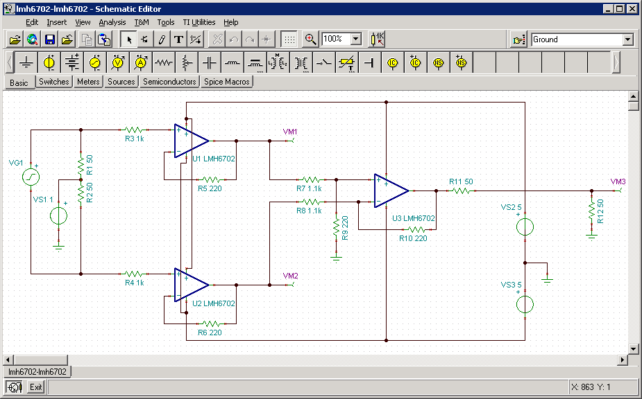
Update: An earlier version of this schematic showed the output of U3 being grounded. That was an error and the ground connection has been removed.
As pointed out by Elliot Williams this is fairly traditional instrumentation amplifier built with separate OP-amps.
I tried a bunch of different OP-amps from the TI libraries but settled on the LMH6702, a “1.7-GHz Ultra-Low Distortion Wideband Op Amp”. It has a high input impedance (1MΩ) when used in a voltage follower configuration and has about twice the bandwidth i need.
The input signal is simulated by a voltage generator (VG1) which outputs a square wave which is then fed to two resistors (R1, R2) centered around a constant voltage source (VS1). This is intended to simulate a 1V LVDS clock signal biased by 1V being fed into a differential termination.
The first stage is a pair of of OP-amps (U1, U2) in voltage-follower configuration. I was a bit worried about oscillation so instead of connecting the voltage follower positive input and feedback directly I’ve added some inputs resistors (R3, R4) and feedback resistors (R5, R6) to avoid this. VM1 and VM2 are measurement points that measure the outputs of the OP-amps.
The second stage is a differencing amplifier (U3) with a less than unity gain (set by R7, R8, R9, R10) which gives a 1:5 attenuation. I’ve read that using an OP-amp to attenuate a signal is supposed to have problems with some OP-amps for reasons having to do with to noise feedback, but it worked in simulation so it should work in real life, shouldn’t it?
For more detail: An almost-GHz active differential oscilloscope probe