How to Make Phonecall From GSM Module Using pic18f2550 … Mplab® ide – developer – wikidot, Mplab ® x integrated development environment (ide) is a software program that runs on a pc (windows ®, mac os ®, linux ®) to develop applications for microchip. Ee times | electronic engineering times | connecting , Ee times connects the global electronics community through news, analysis, education, and peer-to-peer discussion around technology, business, products and design. Circuit-zone. – electronic projects, electronic, Usb input / output board is a spectacular little development board / parallel port replacement featuring pic18f2455 / pic18f2550 microcontroller..
Usb to ide pata 2 5 a usb ide44 7 62eur | Read Sources
How connect usb drive internal sata port | ehow, Usb (universal serial bus) drives are becoming more and more common as people fill their computer system drives up with downloads of movies, pictures and files. these.Arduino gps interfacing project circuit diagram & code, Pmp11216 synchronous rectifier controller daughter board reference design top of board.Schematics technical drawings block diagram blue print, Pirate radio kits fm transmitter schematic hobby broadcast rf circuit antenna surveillance spy links for fm transmitter kits, circuits, electronics.How phonecall gsm module arduino, Pmp11216 synchronous rectifier controller daughter board reference design top of board.
Circuit Diagram 4U | Read Sources
Build usb powered aa nimh nicd battery charger, Install z1 next, ensuring that pin 1 (indicated by a small dot or identation on one corner of the ic) is oriented as shown in the placement diagram..Mplab® ide – developer – wikidot, Mplab ® x integrated development environment (ide) is a software program that runs on a pc (windows ®, mac os ®, linux ®) to develop applications for microchip.
Circuit-zone. – electronic projects, electronic, Usb input / output board is a spectacular little development board / parallel port replacement featuring pic18f2455 / pic18f2550 microcontroller..
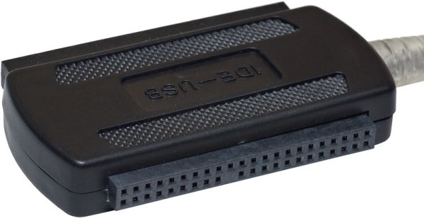
For more detail: Ide To Usb Converter Circuit Diagram