High resolution capacitance meter measures in 0.01pF digits. Total range 0pF to 50uF. – 27th Jun 2011, Updated 25th may 2013.
Another PIC based capacitance meter?
Although there are a few PIC based “pico” capacitance meters on the internet this design has some advantages over the other designs I have seen;
1. It has very high resolution; from 6 to 7 digits! (Others have 3 or 4 digits)
2. It has a wide range; 0pF to 50uF. (Others do not go over 0.1uF or 1uF)
3. It uses only a single cheap PIC 16F628. (Others use two ICs)
4. It does not need calibration! (Others need calibrating with a special test cap)
5. It can do auto-zeroing, floating zero and negative capacitance (relative to zero). 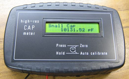
How it works
For absolute simplicity I used a PIC16F628. The oscillator uses the PICs internal comparator so no second IC is needed.
The oscillator is an RC comparator oscillator that switches between 1/3 Vdd and 2/3 Vdd, this is a proven system and the frequency is reasonably unaffected by small changes in the 5v Vdd.
The three 1k5 resistors (green) set the threshold voltages at 1/3Vdd and 2/3Vdd when the comparator output switches. (The PIC is a better comparator than many dedicated comaprator ICs as its output has good push-pull low-Rds FETs).
The oscillation period (freq) is set entirely by RT and CT. RT is a 1% metal film resistor which I measured on my multimeter at 10.00 kohm. Now the only thing that sets the oscillation period is the test cap CT.
The final stage is the PIC timer, that measures the oscillation period very precisely compared to the PICs xtal. And a math calc is done to scale the period to capacitance in farads.
Precision period measuring!
The PIC measures the RC oscillation period by using the PIC’s internal hardware capture (CCP1). The PIC xtal is 16MHz so the PIC timer runs at 4MHz.
It adds consecutive captured periods until there is a total accumulated time greater than 2 million counts (>0.5 second). The only error can be the edge error for the first and last capture, so the error is limited to 1 part in 2 million at each end, a total possible error of 1 PPM (1 Part Per Million).
Now it has a precise captured total of periods the average period is determined by dividing the total period with the number of periods captured. As the total is always just over 2 million it is scaled up to 2 billion before the division, to give a lot of accurate decimal digits after the division.
For example;
“10nF” cap, oscillates about 435Hz
218 consecutive periods are captured, a total of 2004597 counts
Math; (2004597*1000)/218 = 2004597000/218 = 9195399
(so the average period is 9195.399 counts)
A second process is used to convert that result to picofarads;
(9195399*100)/scale = 919539900/919 = 1000587
1000587 is then displayed as; 10005.87 pF
Another small cap example;
“100pF” osc about 43500 Hz
21751 periods are captured, a total of 2000091 counts
Math; 2000091000/21751 = 91953
Scaling; 91953000/919 = 100057
100057 is truncated and displayed as 100.05 pF
All the math and scaling systems have been chosen to give the best precision possible from the 32bit unsigned long variables used in the firmware, without resorting to float or 64bit variables that would have needed a larger and more expensive PIC.
There are three display ranges;
0pF to about 18000 pF, format; “PPPPP.DD pF”
18nF to 999nF, format; “NNN.DDD nF”
1uF to 50uF, format; “UU.DDDD uF”
Display accuracy?
In the pF display mode the display accuracy is about two final digits; +/- 0.02pF.
In the nF and uF mode the display accuracy is better, at +/- 1 final digit.
“Real” accuracy! 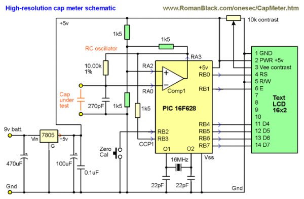
The “real” accuracy depends on the internal calibration, with my PIC, 10.00 kohm resistor and 16MHz xtal the calbration is accurate to better than about 0.2% of the capacitor value, based on some test caps.
You should be able to improve this further by using a trimpot in series with the 10k resistor (ie; 9.75k resistor + 0.5k trimpot) and trimming for much better than 0.2% accuracy by using some precision test caps. However the cap meter was designed for better than 1% accuracy as a convenient hobbyist build without needing any special equipment or special caps.
The benefit of having the high display resolution (lots of digits) is that it allows caps to be compared to each other, and allows fine resolution capacitance changes to be seen, especially things like thermal changes and variable capacitors.
Even with a fixed cap you can see the cap value change as you waft cool air at it with a book and cool it a fraction of a degree. Or you can see the capacitance rise by 0.01pF when you place your finger 1 inch away from the cap!
For more detail: High res cap meter with PIC 16F628