Summary of Worlds Most Useless Machine Rebuild
In 2012, the author rebuilt Claude Shannon's "Ultimate Machine" to fix previous electronic flaws and enhance user suspense. The new design features a locking mechanism to prevent premature opening, ensuring users only interact via the power switch. The microcontroller automates the sequence of latching power, unlocking, extending an arm, and resetting upon switch-off, using solid-state relays for reliable operation.
Parts used in the Ultimate Machine Rebuild:
- Wooden box from Michael Craft Stores
- 1/2 inch plywood
- Craft balsa wood
- Microcontroller
- Solid State Relays (Opto Isolators)
- 9V Battery
- 7805 5V voltage regulator
- NPN Transistor
- Diode
The Original Build
Back in 2009 I build my first copy of a “worlds most useless machine” from a video I found on wimp.com, it is no longer posted, which was a copy of the real original by Claude Shannon called the ultimate machine. The original box was built quickly over the course of one weekend and worked for a few weeks. However the electronic circuit had a few flaws due to me trying to save costs. I was trying to power the servo’s and the electronics from the same batteries which caused some problems and ended up frying my microelectronic. 3 years later and I decided to revive the box and make some improvements to both the electronics and the operation of the box. With the original box most people were skeptical when I handed it to them and told them to turn it On, they always wanted to open the lid first. So I decided to add a lock to the box, so they can’t open it. The only thing they can do is turn on the switch, which adds to the suspense. It really is fun to watch people see the box for the first time.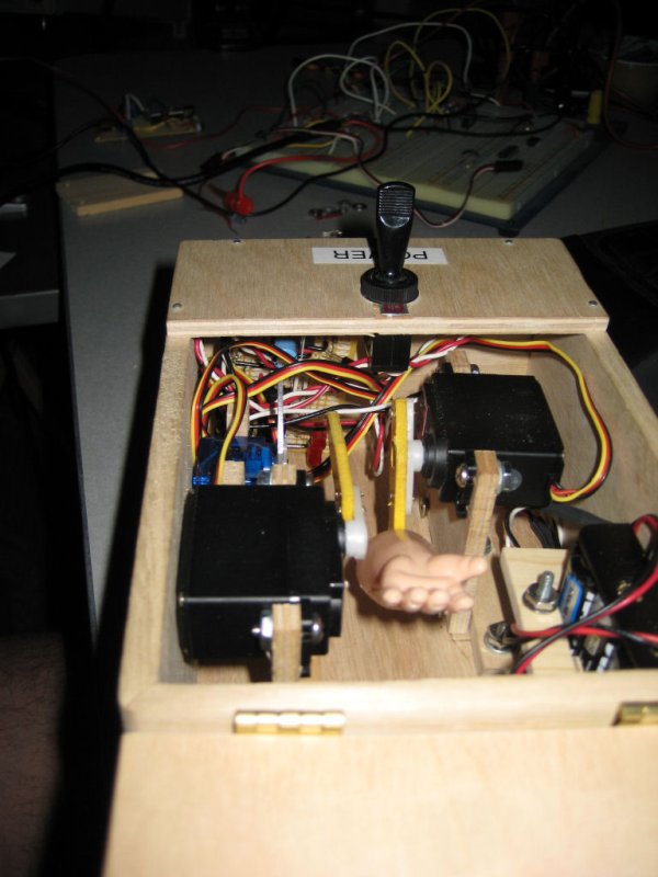
Building the Box
The base box used in the prototype was a cheap wooden box purchased from Michael Craft Stores. I replaced the lid with a small piece of 1/2″ plywood that I cut to make the two halves. The side with the switch is nailed on while the flap side was attached with the boxes original hinges moved to the side. The servo mounts and battery holder are made out of craft balsa wood.
Schematic and Design
Basic Logic Flow:
- User Turns On Power
- MicroController Powers On
- MicroController Turns on Solid State Relay that Latches on the Power Switch. The Microcontroller Turns on a second Solid State Relay which controls power to the servos.
- MicroController Opens the Lock
- MicroController Opens the Lid
- MicroController Moves the Arm Out
- Once the MicroController Detectes the switch has been turned off it then Moves the Arm In
- MicroController Closes the Lid
- MicroController Closes the Lock
- The MicroController then turns off both solid state relays which kills the power to itself and the servos.

Circuit Components:
Control Power, Circuit and Switch
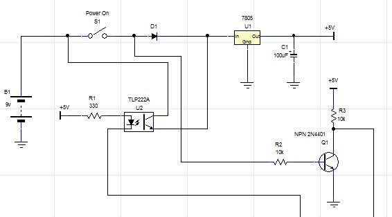
The Microcontroller and switch and powered from a 9V (B1) battery. Power flows from the battery through the switch to the input of a 7805 (U1) 5V voltage regulator. The 7805 supplies the 5V that are required to drive the MicroController and Solid State Relays (Opto Isolators). Once the switch has been turned on and the MicroController has received power a solid state relay (U2) is turned on to Latch on the power switch, effectively shorting out the switch to keep power on even if the switch is turned off. A Diode (D1) keeps power from flowing back from the solid state relay to the output of the switch. The Diode is needed so that the microcontroler can read the state of the switch, without it it would always have voltage potential because of the Latched Power. The State of the Switch which is 9V is also feed to a NPN Transistor (Q1). The transistor acts as a simple switch to switch a 5V source on and off so the MicroController can safely read the state.
For more detail: Worlds Most Useless Machine Rebuild
- Why did the original machine fail?
The electronic circuit had flaws because the author tried to power servos and electronics from the same batteries, which fried the microelectronic. - What improvement was added to increase suspense?
A lock was added so users cannot open the lid first and must turn on the switch. - How does the microcontroller keep the power on after the switch is flipped off?
A solid state relay latches onto the power switch, effectively shorting it out to maintain power. - What component regulates the voltage for the microcontroller?
A 7805 5V voltage regulator supplies the required 5V to drive the microcontroller and solid state relays. - Why is a diode needed in the circuit?
The diode prevents power from flowing back from the solid state relay to the switch output, allowing the microcontroller to read the switch state correctly. - How does the system detect when to retract the arm?
The microcontroller detects that the switch has been turned off before moving the arm back in. - What material was used to make the servo mounts?
Craft balsa wood was used to create the servo mounts and battery holder.