Summary of WIRELESS REMOTE CONTROL for Raymarine ST4000 Autopilot using PIC16F628
This article describes a DIY wireless remote control for the Raymarine ST4000+ autopilot, replacing an old wired unit with a 433MHz radio system. The project uses two PIC16F628 microcontrollers paired with Parallax transmitter and receiver modules to enable keypress commands via a membrane keypad. Powered by a 9V battery with power-saving firmware, the handheld transmitter sends data to a stationary receiver connected to the boat's Seatalk interface.
Parts used in the Wireless Remote Control for Raymarine ST4000 Autopilot:
- PIC16F628 microcontroller (pair)
- Parallax 433MHz transmitter module
- Parallax 433MHz receiver module
- Antennas (for both Tx and Rx units)
- Membrane keypad
- Plastic box enclosure
- 9V battery
- Seatalk interface components
- 10MHz XTAL oscillator
- LED indicator
I had designed a remote unit for my ST4000+ autopilot. It did prove out the concept and I used it a lot, but it sported an unsightly coil cord (and of course unsightly coil cords have no place on boats) so I decided to build a wireless remote. The system (handheld Tx unit and stationary Rx unit) is based on a pair of microcontrollers and a pair of 433MHz radios.
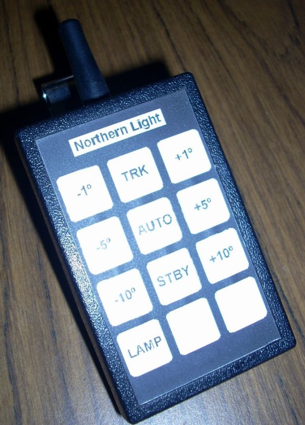
The keypad/transmitter is on the left. It consists of a PIC16F628 microcontroller, Parallax 433MHz transmitter module ( and antenna, and membrane keypad built into the plastic box. It’s powered by a 9V battery. Power saving firmward allows it to run continuously for several months…there is no power switch. The receiver is on the right (above.) It consists of a Parallax 433MHz receiver module and antenna, PIC16F628 microcontroller, and Seatalk interface components. Schematic and firmware details are below.
Code:
/****************************************************************************

seatalk_wireless_remote_tx_1.c

This program is a remote control transmitter that sends a RxCx
number in an eight-byte message sentence with checksum.

Message protocol to the wireless receiver
* Each 9600 baud message contains a command and checksum:
   0xff    // wake up the transmitter and receiver
   0xff    // wake up the transmitter and receiver
   0xff    // wake up the transmitter and receiver
   'J'     // character
   'S'     // character
   'F'     // character
   cMsgCode   // which key was pressed
   'J' + 'S' + 'F' + cMsgCode   // equals checksum

                    +5
                    |
                    14
                ----------
      R4 ----6-| B0    A0 |-17-- out to Parallax 433MHz transmitter
      R3 ----7-| B1    A1 |-18-- out to LED
      R2 ----8-| B2       |
      R1 ----9-| B3       |
      C3 ---13-| B7       |
      C2 ---12-| B6       |
      C1 ---11-| B5       |
               |          |
 10MHz XTAL-15-|  16F628  |
       XTAL-16-|          |
                ----------
                     5
                     |
                    Gnd

          KEYBOARD ASSIGNMENTS
            C1      C2      C3
        +------------------------+
    R1  |      (cable here)      |
        |                        |
    R2  |                        |
        |                        |
    R3  |                        |
        |                        |
    R4  |                        |
        +------------------------+

***************************************************************************/
For more detail: WIRELESS REMOTE CONTROL for Raymarine ST4000 Autopilot using PIC16F628
- What is the main purpose of this project?
To replace an unsightly coil cord on an ST4000+ autopilot with a wireless remote using 433MHz radios. - How does the system transmit data?
The transmitter sends an eight-byte message sentence containing a command and checksum at 9600 baud. - What microcontroller is used in the design?
The project utilizes a pair of PIC16F628 microcontrollers for both the transmitter and receiver. - Can the device run continuously without a power switch?
Yes, power-saving firmware allows it to run for several months on a single 9V battery without a power switch. - How is the wake-up sequence initiated?
The system wakes up by sending three consecutive 0xff bytes before the character J, S, F, and the message code. - What interface connects the receiver to the autopilot?
The receiver connects to the autopilot via Seatalk interface components. - Does the transmitter require a physical cable connection?
No, the transmitter is a standalone unit powered by a 9V battery and communicates wirelessly. - What frequency do the radio modules operate on?
The system uses 433MHz radio modules for communication between the handheld and stationary units.