


Summary of Very Accurate LC Meter based on PIC16F628A using pic microcontroller
This article details a DIY Accurate LC Meter capable of measuring inductance and capacitance with 1% accuracy. It features automatic ranging, a 16x2 LCD display, and uses an LM311 IC for frequency generation alongside a pre-programmed PIC16F628A microcontroller for calculations. The device operates on 6-16V and includes specific high-precision components like WIMA capacitors and metal film resistors to ensure reliable readings across various ranges.Parts used in the Accurate LC Meter:
- 1x 16x2 LCD Display with Green / Blue Backlight
- 1x PIC16F628A Programmed Microcontroller
- 1x LM311 IC
- 1x Accurate LC Meter PCB with red solder mask
- 1x Enclosure
- 1x Gold Plated Machined 18 DIP IC Socket
- 1x Gold Plated Machined 8 DIP IC Socket
- 1x L/C Pushbutton Switch with Black Cap
- 1x Tactile momentary reset switch with Black Cap
- 1x Gold Plated 16-PIN LCD Female Header
- 1x Gold Plated 16-PIN LCD Male Header
- 1x Gold Plated 2-PIN Header
- 2x Gold Plated 1-PIN Header
- 1x 4.000 MHz Crystal
- 1x High Precision 82uH Inductor
- 1x 5V Ceramic Reed Relay
- 1x LM7805 Regulator
- 1x 10K LCD Contrast Trimmer
- 2x 1000pF High Precision WIMA Capacitor
- 1x 100nF High Quality WIMA Capacitor
- 2x 10pF High Stability Capacitor
- 2x 10uF Panasonic Capacitor
- 1x 10 1% Metal Film Resistor
- 1x 1K 1% Metal Film Resistor
- 2x 6.8K 1% Metal Film Resistor
- 1x 47K 1% Metal Film Resistor
- 3x 100K 1% Metal Film Resistor
|
|
 About Accurate LC Meter
|
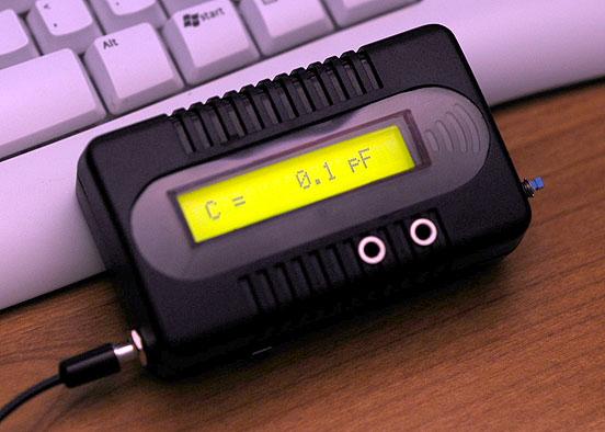
This is one of the most accurate and simplest LC inductance / capacitance Meters that one can find, yet one that you can easily build yourself. This LC Meter allows to measure incredibly small inductances starting from 10nH to 1000nH, 1uH to 1000uH, 1mH to 100mH and capacitance from 0.1pF up to 900nF. LC Meter's circuit uses an auto ranging system so that way you do not need to spend time selecting ranges manually. Another neat function is reset switch that will reset the initial inductance / capacitance, making sure that the final readings of the LC Meter are as accurate as possible. |
Special Edition Accurate LC Meter Kit
|
Special Edition LC Meter Kit includes top notch high precision components that are only found in premium quality kits. It includes high quality double-sided printed circuit board (PCB) with red solder mask and pre-soldered tracks for easier soldering, LCD display with yellow-green LED backlight, programmed PIC16F628A microcontroller chip, high precision capacitors and inductor, 1% Metal Film resistors, Machined IC Sockets, gold plated header pins, LCD header connectors and all the other components that are needed to build a premium quality kit. Thanks to the use of LCD connectors LCD display can be detached from the main PCB board at any time even after the kit has been assembled. Special Edition Accurate LC Meter is designed for professionals that require unprecedented measurement accuracy and offers great value at low cost. |
How does LC Meter Work?
|
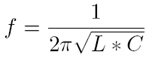
To be able to determine the value of an unknown inductor / capacitor we can use the frequency formula given below.
Note that there are three variables that we can work with; f, L and C (f represents a frequency, L inductance and C capacitance). If we know the values of the two variables we may calculate the value of the third variable. Lets say we want to determine the value of an unknown inductor with X inductance. We plug X inductance into the formula and we also use value of a known capacitor. Using this data we can calculate the frequency. Once we know the frequency we can use the power of the algebra and rewrite the above formula to solve for L (inductance). This time we will use the calculated frequency and a value of a known capacitor to calculate the inductance. Isn't this amazing? We just calculated the value of unknown inductor, and we may use the same technique to solve for the unknown capacitance and even frequency. |
Applying the Theory to LC Meter's Hardware
|
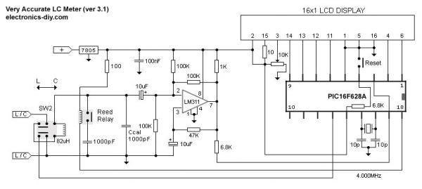
Now let's use the above theory and apply it to electronics. The LC Meter uses a popular LM311 IC that that functions as a frequency generator and this is exactly what we need. If we want to calculate the value of an unknown inductor we use a known Ccal 1000pF capacitor and the value of an unknown inductor. LM311 will generate a frequency that we can measure with a frequency meter. Once we have this information we can use the frequency formula to calculate the inductance. The same thing can be done for calculating the value of a unknown capacitor. This time we don't know the value a capacitor so instead we use the value of a known inductor to calculate the frequency. Once we have that information we apply the formula to determine the capacitance. All this sounds great, however if we want to determine the value of a lot of inductors / capacitors then this may become a very time consuming process. Sure, we can write a computer program to do all these calculations, but what if we don't have an access to a computer or a frequency meter?
In the next step we use the frequency generated by LM311 IC and pass it on to PIC 16F628A's PIN 17. We designate this PIN as an input, as well as all other PINs that are directly connected to switches. User can use these inputs to tell the microcontroller to execute specified set of instructions or perform calculations. Once the microcontroller will calculate the unknown inductance or capacitance it will use PINs that are designated as outputs and pass the results onto the 16 character green backlighted LCD display. |
LC Meter's Switches
|
Reset Switch - Resets capacitance / inductance readings |
For more detail: Very Accurate LC Meter based on PIC16F628A
- How does the LC Meter calculate unknown values?
The meter uses the frequency formula involving frequency, inductance, and capacitance; it measures a generated frequency using known values to solve for the unknown variable. - What role does the LM311 IC play in the circuit?
The LM311 IC functions as a frequency generator that produces a measurable frequency based on known and unknown components. - Can I manually select measurement ranges?
No, the LC Meter features a full automatic ranging system so you do not need to spend time selecting ranges manually. - What is the purpose of the reset switch?
The reset switch resets the initial inductance or capacitance reading to ensure the final measurements are as accurate as possible. - Why is the PIC16F628A microcontroller necessary?
The microcontroller executes HEX programs to perform the algebraic calculations required to determine the unknown value without needing a computer during operation. - Does the kit include a programmed microcontroller?
Yes, all Accurate LC Meter kits come with a microcontroller that is already programmed and ready to be used. - What voltage supply range does the meter require?
The LC Meter requires a voltage supply between 6 and 16 volts. - How can I test the LM311 oscillator?
You can ground PIC16F628A PIN12 to display the initial frequency of the LM311 oscillator, which should be around 550KHz. - What is the resolution for inductance measurement?
The inductance resolution is 10nH. - Is the LCD display detachable after assembly?
Yes, thanks to the use of LCD connectors, the display can be detached from the main PCB board at any time even after the kit has been assembled.
Related projects
DHT11 Low Cost Humidity Sensor using PIC16F628A with Proteus Simulation
IntroductionThis microcontroller project demonstrates how to interface a low-cost DHT11 temperature and humidity sensor with a PIC16F628A using a Proteus simulation environment.The...
LCD & Display Projects · PIC16F628AFrequency Counter by PIC16F628
In this project we are building a basic and low cost frequency counter circuit . It can measure from 16Hz to 100Hz...
Games, Toys & Calculators · PIC16F628ATIC TAC TOE game using PIC16F628
This project is not to introduce Tic Tac Toe. Everyone knows this game. It's to introduce two features. Bi-coloured LEDs, microcontrollers and...
Meters & Test Instruments · PIC16F688Determine capacitance by measuring the charging time using PIC16F688
When TEST botton is pressed, RA3 pin is set to "1". R2 and R3 are divide the voltage to 1/2 Vra3 which...
Meters & Test InstrumentsFrequency Meter Using Microcontroller
This tutorial simply states how to calculate frequency of a pulse source using a microcontroller. Story https://youtu.be/NAoj-HLRIro This tutorial simply states how...
Meters & Test Instruments · PIC16F84ADigital thermometer with PIC16F84 circuit
This electronic project is a very simple thermometer that is based on the PIC16F84A microcontroller, designed by Microchip. Why to use a...

Ibrar Ayyub
I am an experienced technical writer holding a Master's degree in computer science from BZU Multan, Pakistan University. With a background spanning various industries, particularly in home automation and engineering, I have honed my skills in crafting clear and concise content. Proficient in leveraging infographics and diagrams, I strive to simplify complex concepts for readers. My strength lies in thorough...