Summary of Using Microcontrollers ( Microchip PIC)
Many beginners can build a microcontroller board with just a few components: power decoupling, optional crystal oscillator, and—if needed—an ISP connector with a reset pull-up and small resistors. Two approaches are: omit ISP and preprogram the chip, or include ISP to reprogram in-system. For PIC micros, add a diode and 4.7k resistors on MISO/MOSI/SCK if those pins also connect to peripherals. Keep the decoupling capacitor close to power pins. Common PIC programmer pinouts exist; single-row connectors are convenient though not always standard.
Parts used in the PIC Microcontroller Board Project:
- Microcontroller (PIC)
- Decoupling capacitor (0.1uF ceramic)
- Crystal oscillator (optional)
- Two capacitors for crystal
- 10k pull-up resistor for RESET
- ISP connector
- 4.7k resistors for MISO/MOSI/SCK (optional)
- Diode (for PIC ISP, as required)
Many people using Arduino or some other development board in their projects, instead of making their own board with microcontroller because they simply don’t know how to design PCB with microcontrollers. What microcontrollers need in order to operate?
This time I will be focusing on two most popular 8 bit micro architectures: PIC Microchip .
In reality what many people are afraid of is really simple to do. You just need a couple of passive components and you’re good to go.
There’s two scenarios you might want to stick with:
- Do not put ISP (In System Programming interface) on the board. Just upload firmware to the micro before inserting it (or soldering it) to the board.
- Put ISP to the board and upload firmware to the chip while device is all assembled and working.
For example you would want to stick with first first scenario when you’ve got fairly simple device and you sure that you wont need to change it’s firmware in future. In that case you can save money on connector and a few resistors. In some cases even on controller with higher pin count, because when you’ve got ISP functionality, you can’t use “reset” pin as a general I/O pin. And sometimes one pin makes all the difference.
Second scenario will allow you to make changes in firmware when everything is soldered and device is working. In most cases you would want to put ISP to the board.
So, what you need to make your own board with microcontroller?
- Microcontroller (I guess.. )
- Decoupling capacitor (usually ceramic 0.1uF)
- Crystal + two capacitors (optional)
That’s it! Usually microcontrollers have everything they need on board. Like internal flash memory, RC oscillator and so on. And from you they need only power.
If you need to be able to upload firmware to microcontroller (for example, like Arduino sketch) using ISP (In System Programming interface), you would also need a couple of resistors and connector (and in case of PIC microcontrollers – a diode).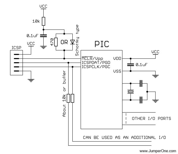
pic microcontroller
In this self-explanatory schematic you can see decoupling capacitor on the right, which must be as close to microcontroller’s power pins as possible; crystal oscillator, which is optional, because you can use internal RC oscillator or external clock signal, depends on your needs; 10k pull-up resistor for RESET pin, to allow external programmer to drive this pin low when uploading firmware; ISP connector. And if you want to use MISO, MOSI and SCK pins for purposes other than firmware upoload, you can connect 4.7k resistors between those pins and peripherals that you want to connect there.
And this is pinout of programming connectors for pic micros:
Two connectors on the left are from the most popular pic programmer made by pic And on the right is the pinout that I’m using in my projects, because it is much easier to work with single row connector than with double row ones. But be aware – it’s not a standard connector pinout.
For more detail: Using Microcontrollers ( Microchip PIC)
- What components are absolutely necessary for a microcontroller to operate?
A microcontroller needs power and a decoupling capacitor; optionally it may use a crystal and two capacitors if an external clock is required. - Do I have to include an ISP connector on my board?
No; you can either omit ISP and upload firmware before soldering the chip, or include ISP to program the microcontroller in-system. - When should I avoid putting ISP on the board?
When the device is simple, unlikely to need firmware changes, and you want to save cost or retain certain pins like reset for general I/O. - What additional parts are needed if I include ISP?
You need a connector, a 10k pull-up on RESET, some resistors (for shared I/O), and for PIC micros a diode may be required. - How should the decoupling capacitor be placed?
The decoupling capacitor must be placed as close as possible to the microcontroller power pins. - Can I use the microcontroller's internal oscillator instead of a crystal?
Yes; many microcontrollers have an internal RC oscillator, so the external crystal and caps are optional. - What resistor values are suggested for MISO/MOSI/SCK when shared with peripherals?
Use 4.7k resistors between those pins and the peripherals if you want to reuse those pins for other functions. - Why might a single-row ISP connector be preferred?
Single-row connectors are easier to work with than double-row ones, though their pinout may not be a standard.