Summary of Using ADC Module of PIC Microcontroller with MPLAB and XC8
This tutorial explains how to use the 10-bit, 8-channel Successive Approximation Register (SAR) ADC module on the PIC16F877A microcontroller with MPLAB and XC8. It details reading analog voltages from sensors like temperature or potentiometers by configuring specific registers to convert real-world signals into digital data for processing.
Parts used in the PIC16F877A ADC Project:
- PIC16F877A Microcontroller
- MPLAB X IDE
- XC8 Compiler
- Potentiometer
- Analog channels AN0 to AN7
- A/D Result High Register (ADRESH)
- A/D Result Low Register (ADRESL)
- A/D Control Register 0 (ADCON0)
- A/D Control Register 1 (ADCON1)
This is our 9th tutorial of Learning PIC microcontrollers using MPLAB and XC8. Till now, we have covered many basic tutorial like getting started with MPLABX, LED blinking with PIC, Timers in PIC, interfacing LCD, interfacing 7-segment etc. If you are an absolute beginner, then please visit the complete list of PIC tutorials here and start learning.
In this tutorial, we will learn How to Use ADC with our PIC microcontroller PICF877A. Most of the Microcontroller projects will involve an ADC (Analog to Digital converter) in it, because it is one the most used ways to read data from the real world. Almost all the sensors like temperature sensor, flux sensor, pressure sensor, current sensors, voltage sensors, gyroscopes, accelerometers, distance sensor, and almost every known sensor or transducer produces an analog voltage of 0V to 5V based on the sensors reading. A temperature sensor for instance may give out 2.1V when the temperature is 25C and go upto 4.7 when the temperature is 60C. In order to know the temperature of the real world, the MCU has to just read the output voltage of this temperature sensor and relate it to the real world temperature. Hence ADC is an important work tool for MCU projects and lets learn how we can use it on our PIC16F877A.
Also check our previous articles on using ADC in other microcontrollers:
- How to Use ADC in Arduino Uno?
- Raspberry Pi ADC Tutorial
- Interfacing ADC0808 with 8051 Microcontroller
ADC in PIC Microcontroller PIC16F877A:
There are many types of ADC available and each one has its own speed and resolution. The most common types of ADCs are flash, successive approximation, and sigma-delta. The type of ADC used in PIC16F877A is called as the Successive approximation ADC or SAR in short. So let’s learn a bit about SAR ADC before we start using it.
Successive Approximation ADC: The SAR ADC works with the help of a comparator and some logic conversations. This type of ADC uses a reference voltage (which is variable) and compares the input voltage with the reference voltage using a comparator and difference, which will be a digital output, is saved from the Most significant bit (MSB). The speed of the comparison depends on the Clock frequency (Fosc) on which the PIC is operating.
Now that we know some basics on ADC, lets open our datasheet and learn how to use the ADC on our PIC16F877A MCU. The PIC we are using has 10-bit 8-channel ADC. This means the output value of our ADC will be 0-1024 (2^10) and there are 8 pins (channels) on our MCU which can read analog voltage. The value 1024 is obtained by 2^10 since our ADC is 10 bit. The eight pins which can read the analog voltage are mentioned in the datasheet. Lets look at the picture below.
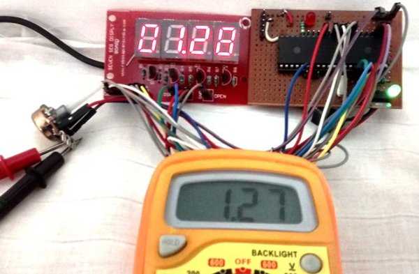
The analog channels AN0 to AN7 are highlighted for you. Only these pins will be able to read analog voltage. So before reading an input voltage we have to specify in our code which channel has to be used to read the input voltage. In this tutorial we will use channel 4 with a potentiometer to read the analog voltage at this channel.
The A/D module has four registers which has to be configured to read data from the Input pins. These registers are:
• A/D Result High Register (ADRESH)
• A/D Result Low Register (ADRESL)
• A/D Control Register 0 (ADCON0)
• A/D Control Register 1 (ADCON1)
For more detail: Using ADC Module of PIC Microcontroller with MPLAB and XC8
- What type of ADC does the PIC16F877A use?
The PIC16F877A uses a Successive approximation ADC or SAR. - How many channels can read analog voltage on this microcontroller?
There are eight pins or channels that can read analog voltage. - What is the output resolution range of the ADC?
The output value ranges from 0 to 1024 because it is a 10-bit ADC. - Which four registers must be configured to read data?
You must configure ADRESH, ADRESL, ADCON0, and ADCON1. - How do you specify which channel reads the input voltage?
You must specify the channel in your code before reading an input voltage. - Why is the ADC module important for MCU projects?
It allows the MCU to read analog voltage outputs from sensors and transducers. - Does the comparison speed depend on the clock frequency?
Yes, the speed of the comparison depends on the Clock frequency Fosc. - Can almost every known sensor produce an analog voltage?
Yes, most sensors produce an analog voltage between 0V and 5V based on readings.