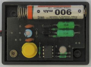
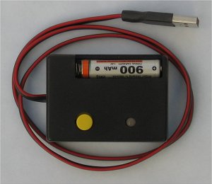
USB Battery Charger Circuit Pic16f629 microcontroller integrated with the computer’s USB port 1 100-1000 The AAA battery charging circuit charging time the battery current compared to 1-14 hours of battery is full time dual-color LED and buzzer and warning… Electronics Projects, USB Battery Charger Circuit with PIC16F629 “battery charger circuit, microchip projects, microcontroller projects, pic assembly example,

USB Battery Charger Circuit Pic16f629 microcontroller integrated with the computer’s USB port 1 100-1000 The AAA battery charging circuit charging time the battery current compared to 1-14 hours of battery is full time dual-color LED and buzzer and warning is given. Besleneeg from the USB port in the circuit diagram for the circuit in 7805 will use a 5 volt regulator IC that you do not want to use the USB port with an adapter 9v 12v going to use … 7805 should be installed .. USB battery charging circuit assembly prepared with the resources of the microcontroller software. Asm and. Hex file there.
PIC16F629 USB BATTERY CHARGER

USB devices may draw from the PC up to 100 mA. The larger current can subscribe only when it is requested in the configuration descriptor and Energy approves the operating system. That in this charger does not, and therefore may not work in any PC. For this reason, the mind staffed capacitor C1, which when turned on will draw a large current for a long time and fungi that can (and should) be evaluated as a short circuit and disconnect the USB port.
Source: http://www.cmail.cz/doveda/konstrukce/aku_usb/index.htm USB Battery Charger Circuit with PIC16F629 pic assembly alternative link:
FILE DOWNLOAD LINK LIST (in TXT format): LINKS-746.zip
