Summary of Trippy RGB Color Mixing NightLight
This article details a DIY "Trippy Crystal Nightlight" using a PICAXE 08M microcontroller, RGB LEDs, and a USB charger. The project replaces traditional download circuitry with on-breadboard programming for simplicity. It utilizes Jell-O containers and Saran Wrap to diffuse light, creating a colorful cycling effect while consuming negligible electricity. Total material costs are approximately $15.
Parts used in the Trippy Crystal Nightlight:
- 5MM Red LED high brightness
- 5MM Green LED high brightness
- 5MM Blue LED high brightness
- Solid core hook up wire 24 gauge
- 20 ohm 1/4 W resistor
- 100 ohm 1/4 W resistor
- 100K ohm 1/4 W resistor
- Perf Board
- Strip Board 1 inch by 5/8 inch
- PICAXE 08M IC
- 8 Pin DIP IC Socket
- USB/AC Charger for MP3 Players
- Jell-O Snack cups
- Saran Wrap
- Sheet metal strip
- Double side foam tape
- Scrap piece of cardboard
- Solderless Breadboard
- AXE029 Breadboard Adapter
- PICAXE Serial Download Cable or USB Download Cable
Project is based on A Trippy Crystal Nightlight by Charles Platt in Make magazine volume 25, see URL below for additional details. A fun and simple project to get started with PICAXE microcontrollers.
http://www. makezine.com/25/electronics
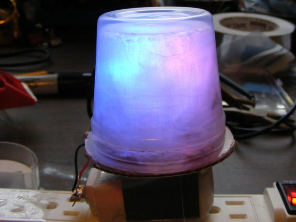
In this version an inexpensive (> $2.50) AC USB charger provides a traditional plug-in-the-wall nightlight form factor. I removed download circuitry from the main circuit board and instead program PICAXE 08M microcontrollers on a separate breadboard – this simplified the main circuit board. Two 2 Jell-O snack size containers and a little bit of Saran Wrap rather than a quartz crystal diffuse the light,
Total material cost about $15.00. The unit has been running constantly without problems for over six months. Electricity usage is almost too low to measure. Watch YouTube video below to see nightlight cycle through its color changes.
Step 1: Parts & Tools List
(QTY) / Description / Source / Part No.
(1) 5MM Red LED high brightness Mouser 696-SSL-LX5093XRC/4 http://www.mouser.com
(1) 5MM Green LED high brightness Mouser 696-SSL-LX5093UEGC
(1) 5MM Blue LED high brightness Mouser 696-SSL-LX5093USBC
(20 inches) solid core hook up wire 24 gauge Mouser, Radio Shack or other
(2) 20 ohm 1/4 W resistor Mouser 66-RC07GF200J
(1) 100 ohm 1/4 W resistor Mouser 588-OD101JE
(3) 100K ohm 1/4 W resistor Mouser 291-100K-RC
(1) Perf Board Radio Shack 276-148
(1) Strip Board 1″ by 5/8″ Mouser 854-ST3U
(3) PICAXE 08M IC http://www.phanderson.com/picaxe/
(3) 8 Pin DIP IC Socket Radio Shack 276-1995 or other
(1) Charger USB/AC for MP3 Players – White http://www.amazon.com/gp/product/B000A2BLEC/ref=ox_ya_os_product
Mechanical
(2) 3.5 oz Jell-O Snack cups Supermarket
(1) Saran Wrap Supermarket
(1) 1 1/4″ by 3″ sheet metal strip Home Depot or Hardware store
(1 ft) Double side foam tape Hardware store or Radio Shack
(1) scrap piece of cardboard about 3″ dia. Supermarket
Programming Tools
(1) Solderless Breadboard Mouser, Radio Shack or other
(1) AXE029 Breadboard Adapter http://www.phanderson.com/picaxe/
(1) AXE0AXE026 – PICAXE Serial Download Cable http://www.phanderson.com/picaxe/
OR
(1) AXE027 – PICAXE USB Download Cable http://www.phanderson.com/picaxe/
(1) PICAXE Program Editor
http://www.picaxe.com/Software/PICAXE/PICAXE-Programming-Editor/
Misc Tools
Hot glue gun
Solder and Soldering Iron
Tin Snips
Step 2: Prepare Power Supply
Preparing the Power Supply
Cut a piece of stripboard a little more than 4 traces wide and about 3/4 inches long.
Sand or file down edges so it fits tightly in USB charger socket with the 4 Traces centered within the socket so you’re making a good connection with left side +5 VDC pin & right side ground pin. Verify that you’re getting a good connection with a multi-meter. Secure stripboard with hot glue.
If you don’t have another 5 VDC power supply to use for programming the PICAXE ICs in the next step
then you can now solder Red (+5VDC) and Black (ground) wires to stripboard. Make wires a little long so you can use it to power the PICAXE chip on the breadboard during programming.
Otherwise you can wait until after you have built the main circuit board to solder the power supply wires.
Tape over USB Charger’s “Power On” red LED to block its light.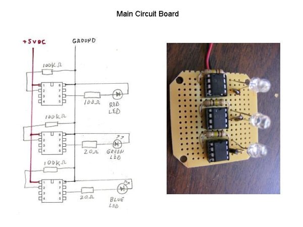
Step 3: Program PICAXE 08M ICs
Program PICAXE 08M Chips
Build up solderless breadboard with PICAXE O8M IC and AXE029 breadboard adapter as shown in photographs.
For additional info – see link below, and/or the PICAXE Manual 1 available from the Programming Editor Help menu.
http://www.picaxe.com/docs/axe029.pdf
Download Programming Editor from PICAXE website and install on your computer. Connect your PC using either Serial or USB cable, and download programs to PICAXE ICs.
For additional help with programming, see the Editor’s Help menu – Manual 1is the most helpful for getting started the first time.
http://www.picaxe.com/Software/PICAXE/PICAXE-Programming-Editor/
You need to program three PICAXE chips, one for each color LED – red, green, and blue. Program code is the same for each LED except for one line of code as shown below.
Red LED: Colorinc =17
Green LED: Colorinc =23
Blue LED: Colorinc =37
This provides an offset so as to get a pleasing mix of color variations. To make it easier, I have attached three separate programs – one for each color of LED.
For more detail: Trippy RGB Color Mixing NightLight
- What is the total material cost for this project?
The total material cost is about $15.00. - How does the unit achieve its crystal-like appearance?
It uses two Jell-O snack size containers and Saran Wrap to diffuse the light instead of a quartz crystal. - Can I program the PICAXE chips without removing the main board?
Yes, you can program the PICAXE 08M microcontrollers on a separate breadboard, which simplifies the main circuit board. - Does the nightlight consume a lot of electricity?
No, the electricity usage is almost too low to measure. - What specific code change is needed for each color LED?
You must adjust one line of code called Colorinc, setting it to 17 for red, 23 for green, and 37 for blue. - How do you prepare the power supply connection?
Cut a piece of stripboard to fit the USB charger socket, ensuring the traces connect to the +5 VDC and ground pins, then secure it with hot glue. - What tools are required to build the mechanical casing?
You need tin snips for the sheet metal, double side foam tape, and scrap cardboard. - How long has the unit been tested?
The unit has been running constantly without problems for over six months.