Summary of Mädchen Machen Technik using pic-microcontroller
This workshop introduces high school students to microcontrollers and digital electronics through a "Blinking Lights" project using the PIC12F629 chip. Students learn circuit measurement, breadboard usage, and LED connections before building a programmer circuit with a PICkit2 device. Finally, they program the chip using MPlab software and assembly code to create custom flashing patterns for up to five LEDs.
Parts used in the Blinking Lights Project:
- PIC12F629 Microcontroller
- PICkit2 Programmer
- Two AA Batteries
- Breadboard
- Five Light Emitting Diodes (LEDs)
- Multi-meter
- Wires
- MPlab Software
- Personal Computer with USB Port
The “Mädchen Machen Technik” workshop is designed to give high school students an introduction to microcontrollers. The students will build a flashing light pattern and/or a counter-timer. In the process of building this project, the students will learn about microcontrollers and digital electronics. Here is the parts list for the projects.
- The students will learn how to measure DC voltage and resistance using a multi-meter. They will measure the voltage of batteries connected in series and in parallel.
- The students are given the task to determine, using a voltmeter and wires, how the holes on a breadboard are connected. The students sketch the hole connections on a picture of the breadboard.
- Next, the students will be given several Light Emitting Diodes (LEDs), with an explanation on how they work. They are to connect the LED(s) to the breadboard so that one LED lights up, then two light up, etc. Do not put more than 3 Volts across an LED.
Building the Circuit
A schematic of the circuit is shown below:
- he PIC12F629 has only 8 pins. Pin 8 is the ground pin, and Pin 1 is the positive voltage pin. In our applications, we will use two AA batteries in series which will give around 3 volts for Pin 1.
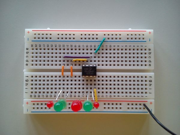
- The other six pins (2-7) will be used as digital input/output. Pins 2, 3, 5, 6, and 7 will be output pins connected to LEDs. Pin 4 can only be set as an input pin. We will not connect an LED to pin 4. In the picture below, one can see the 5 LEDs connected to the appropriate pins.
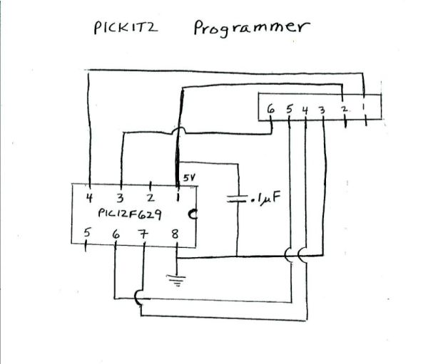
he programmer has 6 pins in a row. The ground on the programmer, pin 3, is connected to the ground of the chip (pin 8). The voltage (5V) of the programmer, pin 2, is connected to pin 1 of the chip. The other programmer pins are connected to the chip as shown in the two figures below:
The pickit2 is connected to a personal computer through a usb port. In the picture below, one can see where the microcontroller chip is connected in the programmer:
Finally, we program the microcontroller using the MPlab software from microchip.
Programming the Microcontroller
- The assembly code we will start with is the code: test12.asm. The only lines of the code the students need to modify for their desired blinking pattern are:loop
movlw b’00100101′
movwf GPIO
call delay1
movlw b’00010010′
movwf GPIO
call delay1
goto loop - First, the binary number ‘00100101’ is placed in the working register. Then this number in the working register is transfered into the register GPIO. The GPIO register is directly connected to the pins of the chip. A “1” will put 3 volts on a pin, and a “0” will put zero volts on the pin. The last 6 bits are connected to pins 2, 3, 4, 5, 6, and 7 respecively. The number ‘00100101’ in register GPIO will result in 3 volts for pins 2, 5, and 7, and zero volts for pins 3 and 6. Pin 4 is not affected, it is only an input pin. The subroutine delay1 causes a delay of around 1/4 second.
for more detail: Mädchen Machen Technik
- What is the main goal of the Mädchen Machen Technik workshop?
The workshop aims to give high school students an introduction to microcontrollers and digital electronics by building a flashing light pattern or counter-timer. - How many LEDs can be programmed to blink in this project?
The microcontroller can produce a blinking pattern for up to five LEDs. - Which specific microcontroller is used for the initial project?
The project uses the PIC12F629, which has only 8 pins. - Can pin 4 on the PIC12F629 be connected to an LED?
No, Pin 4 can only be set as an input pin and should not have an LED connected to it. - How are two AA batteries configured to power the circuit?
The two AA batteries are connected in series to provide around 3 volts to Pin 1 of the chip. - What voltage limit must be observed when connecting an LED?
Students must not put more than 3 Volts across an LED. - Which software is used to program the microcontroller?
The MPlab software from Microchip is used to program the microcontroller. - How does the binary number in the GPIO register affect the pins?
A "1" puts 3 volts on a pin while a "0" puts zero volts, controlling which LEDs light up based on the last 6 bits.