Summary of Toggle/Blink led on specific delay with pic microcontroller using timers: MPLABX and xc8 compiler
This tutorial shows how to toggle LEDs using PIC microcontroller timers to generate precise delays (example: 10 ms with a 20 MHz clock and 1:4 prescaler). It explains timer count calculation (Timer Count = 12500 = 0x30D4), loading TMRxH/TMRxL, circuit notes for PIC16F887 with eight LEDs on PORTB, and provides MPLAB X/XC8 code where Timer1 in 16-bit mode produces the delay inside Timer0Delay.
Parts used in the Toggle/Blink led on specific delay with pic microcontroller using timers: MPLABX and xc8 compiler:
- PIC16F887 microcontroller
- 20 MHz crystal
- Eight LEDs
- 330 ohm resistors (one per LED)
- Wiring/breadboard or PCB
- MPLAB X IDE
- XC8 compiler
- Power supply (external Vcc for recommended LED configuration)
In the previous tutorial we discussed about how to generate a specific delay using internal timers of pic microcontroller. We also derived and discussed the formula for calculating the output signal period. We also discussed the terms related with the time/frequency formula derivation, such as Tick_counter frequency, Timer Count etc. This tutorial is in chain with the previous one the code used below in inherited from the previous tutorial. I recommend to first go through the previous simple tutorial. You can easily understand the code below if you take the tutorial
Now you have taken the above tutorial its time to start with this tutorial. Suppose we want to toggle an led, generate and event or read data after 10 ms with 20 Mhz clock source. I selected the prescaller to be 1:4. For this we have to calculate the “Timer Count” value. Lets start deriving the “Timer Count”. The formula is given below.
Specific delay formula for Pic Microcontroller’s

10 ms = Timer Count * ( 4 / (20M hz/ 4) )
10 ms = Timer Count * ( 4 / 5 Mhz)
10 ms * 5 M hz = Timer Count * 4
50 k = Timer Count * 4
50000 / 4 = Timer Count
Timer Count = 12500 (Hex 0x30D4)
TMR1H = 0x30;
TMR1L = 0xD4;
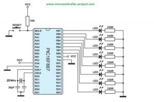
Project circuit diagram
Note: Led’s anode is connected to pic microcontroller port-b pins and cathode is grounded with 330 ohm resistor placed in series. This configuration of led’s is a bad choice. I recommend you to connect the anode of led’s with external power source and connect the cathode with port-b pins of pic microcontroller. Resistor must be placed in series with the led to limit the current consumption by led.
My circuit configuration also worked but the led lights are too dim and its hard to see the effect of blinking/toggling in bright day light. I switched of room lights to see the clear pic microcontroller blinking led effect.
| /************************************************** | |
| * Property of: www.microcontroller-project.com * | |
| * Author: Usman Ali Butt * | |
| * Created on 11 April, 2017, 2:30 PM * | |
| **************************************************/ | |
| #include <stdio.h> | |
| #include <stdlib.h> | |
| #include <pic16f887.h> | |
| void Timer0Delay(void); //Delay Function | |
| int main(int argc, char** argv) { | |
| TRISB=0x00; //Port-B as Output | |
| while(1){ | |
| PORTB= ~PORTB; //Toggle Output | |
| Timer0Delay(); //Delay | |
| } | |
| return (EXIT_SUCCESS); | |
| } | |
| void Timer0Delay(void){ //10ms delay | |
| T1CON=0x01; //Timer-1 16-bit mode Prescaler 1:4 | |
| TMR1H=0x30; //Count Hight Byte | |
| TMR1L=0xD4; //Count Low Byte | |
| T1CONbits.TMR1ON=1; //Run timer | |
| while(INTCONbits.TMR0IF==0); //Wait for flag to over flow | |
| T1CONbits.TMR1ON=0; //Switch off timer | |
| INTCONbits.TMR0IF=0; //Clear Interrupt | |
| } |
T1CON=0x01; //Timer-1 16-bit mode Prescaler 1:4
TMR1H=0x30; //Count High Byte
TMR1L=0xD4; //Count Low Byte
- How is a 10 ms delay calculated for a 20 MHz clock with prescaler 1:4?
The tutorial shows 10 ms = Timer Count * (4 / (20 MHz/4)), yielding Timer Count = 12500 (0x30D4). - How is the 16-bit timer value loaded into registers?
Load the high byte into TMRxH (0x30) and low byte into TMRxL (0xD4) for the 0x30D4 value. - Which timer is used in the provided code to generate delay?
Timer1 is used in 16-bit mode to generate the specific delay. - Which microcontroller port is used to connect LEDs?
Port B of PIC16F887 is used; all eight LEDs are connected to PORTB pins. - What clock source is used in the project?
An external 20 MHz crystal is used as the input clock source. - How is the timer started and stopped in the code?
T1CONbits.TMR1ON is set to 1 to run the timer and set to 0 to stop the timer in Timer0Delay. - How does the code detect timer overflow to end the delay?
The code waits while INTCONbits.TMR0IF equals 0, and clears INTCONbits.TMR0IF after stopping the timer. - What development tools are required for this project?
The project uses MPLAB X IDE and the XC8 compiler to build the code. - What LED connection does the author recommend?
Connect LED anodes to an external power source and cathodes to PORTB pins with series resistors, rather than driving anodes from the port.