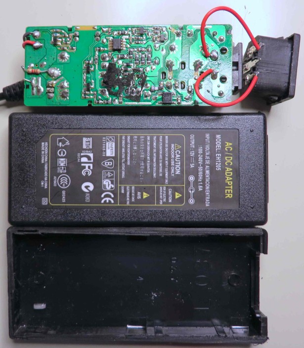
First on the chopping block, the “EH1205”. Wait! What’s this? The original AC connector is mounted to the PCB. Yes, this has been repackaged!
I think we can assume the approvals on the label are fiction. The current rating sure is.
Note the ~5mm spark-gap in the upper left (~15kV?).
Yes! Can you believe it? This board used to be in another adapter housing, or more likely, in an end-product. It seems Chinese manufacturing has sunk to a new low: repackaging used and/or surplus power supplies. On the plus side…recycling.
he original PSU actually appears to be of decent quality. There’s a robust EMI filter and 105° caps (or so they say). Note the cut DC wires and tacked-on LED. The cap adhesive has released. Caps are 400V & 25V.
There are two output diodes, paralleled from the dual TO-220 package. The board was held in place by two pieces of foam, which you’ll see is pretty high-end packaging, relatively speaking.
Next up, the “XY1205A”, again with its fictitious approvals & specs. Nothing horrifically wrong here, unless you count the tacked-on wires and lack of mounting. Good clearance between primary and secondary sides, except where there isn’t.
The board as it came out of the case. The metal plate is not part of the heat sink, but sticky-foamed to the transformer, serving no real purpose. This makes me think we have another repackaged power supply!
Removing the plate reveals the simplest circuit of the batch: No EMI filter (though space for one), no controller. The caps are 400V & 25V, “105°”.
The third adapter I opened provided a real surprise. Can you spot it before reading the caption?
This is good quality guts paired with a botched repackaging job. The original operation of this PSU was intermittent, responding to jiggling of the output wire. I now see it wasn’t because of a loose connection, but because the wires of the original, cut-off connection are essentially touching! Fortunately, the original AC wires aren’t touching, because they’re right on the line input of course – no fuse but the one in my breaker panel! Yikes.
Otherwise, it looks good. The input cap is a 400V 105° UCC/NCC part. Output is 25V, 105°. Both are unfortunately close to hot spots though.
As far as I can tell, the production date is ca. 2000-2001 (board:0093, AC rectifiers:0062). Ugh. Wonder if the board had seen service before being repackaged.
The two blue caps at the upper left are 2.2nF parts in series, bridging primary to secondary sides in parallel with the 88MΩ of resistance. What’s the goal here? Preventing charge buildup on the otherwise isolated output? EMI control?
For more detail: Teardown: 12V AC adapters – The Horror

