Summary of Build a PIC controlled DDS VFO, 0 to 6 MHz using pic microcontroller
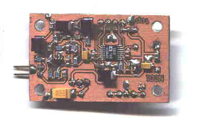
This article describes a PIC-controlled Direct Digital Synthesis (DDS) Variable Frequency Oscillator (VFO) project capable of generating frequencies between 135.7 kHz and 137.8 kHz with high precision. It provides downloadable schematics, PCB layouts, assembly source code for PIC16F84/C84 microcontrollers, and compiled hex files. The system features an LCD display, rotary encoder, and momentary pushbuttons for calibration and locking functions.
Parts used in the PIC Controlled DDS VFO:
- PIC16F84 or PIC16C84 microcontroller
- Hitachi HD44780 controller chip LCD module
- AD9832 DDS component
- Lowpass filter
- EEPROM for calibration storage
- Momentary pushbuttons (LOCK, DFCW, CAL)
- Rotary encoder
- CC5X C compiler software
Files contained in MINIDDS.ZIP:
  readme.txt      Read this first!
  compplac.pdf    Component placement in PDF format
  schema.pdf      Schematic diagram in PDF format
  top.ps          PCB top copper layer in Postscript format
  bottom.ps       PCB bottom copper layer in Postscript format
  ad9832_4.asm    PIC assembly source code
  p16f84.inc      Needed for assembly of ad9832_4.asm (for 'F84)
  p16c84.inc      As above but for 'C84
  vfo5x7f.hex     PIC16F84 program for LCD with 5x7 font
  vfo5x10f.hex    PIC16F84 program for LCD with 5x10 font
  vfo5x7c.hex     PIC16C84 program for LCD with 5x7 font
  vfo5x10c.hex    PIC16C84 program for LCD with 5x10 font
  filtresp.pcx    Computed frequency response of lowpass filter
 Download MINIDDS.ZIP (186K)
Download MINIDDS.PDF (209K)
If you prefer to control the DDS module from a PC (instead of using a PIC), try this:
Download PCVFO.ZIP (18K)
The zip archive contains a single file, VFO.EXE. It is a DOS program but it runs fine in a Windows 95/98 “DOS bubble” as well (see screenshots above).
Are you looking for a DDS based 136 kHz longwave transmitter exciter?
Have a look at G0MRF’s page
Specifications:
- Start-up frequency: 137.00000 kHz
- Tuning range: 135.70000 to 137.80000 kHz in 0.25 Hz steps
- DFCW offset: 0 to 50 Hz adjustable in 0.25 Hz steps
- The dial can be locked to prevent inadvertent QSY
- Calibration: +/- 200 ppm, stored in EEPROM.
- Actual DDS output frequency is 4 * dial frequency
Schematic and source code for the PIC controller is available here:
Download the PIC program lwex.zip
 Almost any 2×16 character LCD module with Hitachi HD44780 controller chip will work. The LCD pin numbers on the schematic are not valid for all LCD modules. Please check the actual signal names on your particular LCD module.
The switches “LOCK”, “DFCW” and “CAL” are momentary pushbuttons.
For more detail: Build a PIC controlled DDS VFO, 0 to 6 MHz
- What is the start-up frequency of this DDS VFO?
The start-up frequency is set to 137.00000 kHz. - Can I control the DDS module from a PC instead of using a PIC?
Yes, you can use the PCVFO.ZIP download which contains a DOS program called VFO.EXE that runs in Windows 95/98. - Does the selected DFCW frequency offset get added automatically?
The selected DFCW frequency offset will be added to the output frequency when the DFCW input is grounded. - What type of LCD module works with this project?
Almost any 2x16 character LCD module with a Hitachi HD44780 controller chip will work. - How precise are the tuning steps for this device?
The tuning range covers 135.70000 to 137.80000 kHz in 0.25 Hz steps. - Is there a way to prevent accidental frequency changes?
The dial can be locked to prevent inadvertent QSY. - What is the relationship between the actual DDS output and the dial frequency?
The actual DDS output frequency is 4 times the dial frequency. - Where is the calibration data stored?
Calibration data with +/- 200 ppm accuracy is stored in EEPROM.